This blogpost continues the series on 4G networks. In the previous article, titled How to Build your Own Personal 4G network, I introduced the main components behind a 4G network and I showed how anyone, with some hardware and some software, could create a 4G network good enough for purposes of testing and research.
In this blogpost I want to dig deeper into the topic, by describing, in all the details I can manage, the stack of protocols used in 4G networks. In the future I would also like to talk about the attach procedure that takes place anytime a UE wants to connect to a 4G core, how cryptography is managed in 4G networks, and what state-of-the-art research with respect to attacking 4G cryptography came out on this topic throughout the years.
Hope it's an interesting read, and let me know if you see any mistake, or if you have some questions about the things mentioned.
#Protocol Stack
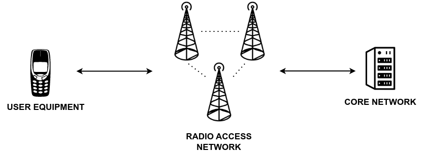
Let's start with a brief recap. Remember, from the previous article, that from a high level abstraction, a 4G network is made up of three main parts:
-
User Equipment (UE): the device that connects to the network.
-
Core Network (EPC): the "cloud" that manages the internal state of the network.
-
Base Station (eNodeB): the middle point that acts as a bridge in order to connect a UE to a core network.
In real 4G network there is not a single base station but a bunch of them, that taken together form the radio access network, also known as E-UTRAN.
In terms of protocol stack, we have three different layers of communication, each of which is made up of different protocols. The layers are, from bottom to top:
- Physical layer
- Data link layer
- Network layer
#Layer n.1: Physical Layer
The physical layer is responsible for transmitting information over the air interface, i.e. over radio signals. This is the layer I'm least comfortable with, given my ignorance when it comes to analog things. Anyhow, I've read that this layers deal with things such as
- Cell searching
- Cell syncrhonization
- Control of transmission power
- Encoding and modulation schemes
I wish these words were meaningful to me, but other than some vague intuition, I cannot say much about these activities.
#Layer n.2: Data Link Layer
Continuing, the second layer starts to become interesting. The data link layer provides services for the upper network layer and also provides mechanisms to grant reliability, confidentiality and integrity to the communications. It is organized into three different protocols. Starting from bottom to top, these protocols are:
- Medium Access Control (MAC)
- Radio Link Control (RLC)
- Packet Data Convergence Protocol (PDCP)
This layer is already much more familar to me, especially in the high level services it offers to the communications. Indeed, the idea of reliability reminds me of TCP, while the concepts of confidentiality and integrity are elementary concepts in cryptography.
Out of all these protocol, it is the job of the PDCP layer to apply encryption in order to prove confidentiality and integrity. For those interested in knowing more about these basic cryptographic properties, I've already written about them in my blogpost about TLS, which stands for Transport-Layer-Security, one of the most famous and important secure network protocols. The blogpost is titled Introduction to TLS.
#Layer n.3: Network Layer
The final layer, the network layer is also organized in three different protocols. In no specific order, these are:
- Non-Access Stratum (NAS)
- Radio Resource Control (RRC)
- Internet Protocol (IP)
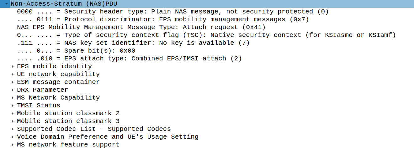
The NAS protocol is the protocol that is used in the
communication between the UE and the core network. NAS messages
are used for example during the attach procedure, which is
executed when the UE wants to join a 4G network. Anytime the UE
wants to kickof the attach procedure, it sends the Attach Request
NAS message, with code 0x41, to the MME. This message contains
various things such a list of UE network capability, which
describe what the UE can do in terms of the supported
cryptography algorithms as well as other services that can be
used between UE and EPC.
The RRC protocol instead is used in the communication between the UE and a base station (eNodeB). It can be used to manage and configure the various radio parameters necessary to keep the communication up and running. RRC messages can also be used to wrap NAS messages. This is exactly how NAS messages sent by the UE are able to reach the core network: first they are wrapped in RRC messages, which are sent to the base station, and then they are unwrapped from the base station and sent to the core network.
The IP protocol is used to connect the base station to the core network, and also to give internet connectivity to the UE, since 4G networks allow devices an entry point to the internet, as any router would. It's just that instead of going directly to the router through a LAN using an ethernet cable and some switch, we first have to go through a base station, using a much more complex set of protocols, some of which also involve radio signals.
#Control Plane
When considering a network architecture as complex as a 4G network, it is important to consider that not all the data that is sent and received in the network is treated in the same way. In particular, we distinguish between the control plane and the data plane as follows:
-
The control plane is the place where all the metadata needed to establish the communication and then keep it running is sent and received. The NAS and RRC protocols for example are part of the control plane. The control plane is also called C-Plane.
-
The user plane instead is the place where all the user data is sent and received. The IP protocol discussed before sometimes belongs to the data plane, because IP packets can contain any sort of application payload, depending on the application in question. Having said that, the IP protocol can also belong to the control plane, depending on the payload it contains. The user plane is also called U-Plane.
In both the control plane and the user plane we have three different types of communication which make use of three different protocol stacks.
-
C-Plane
- UE \(\leftrightarrow\) eNodeB
- eNodeB \(\leftrightarrow\) MME
- eNodeB \(\leftrightarrow\) eNodeB
-
U-Plane
- UE \(\leftrightarrow\) eNodeB
- eNodeB \(\leftrightarrow\) MME
- eNodeB \(\leftrightarrow\) eNodeB
We shall now describe the protocol stack for each type of communication, first for the control plane, and then for the user plane.
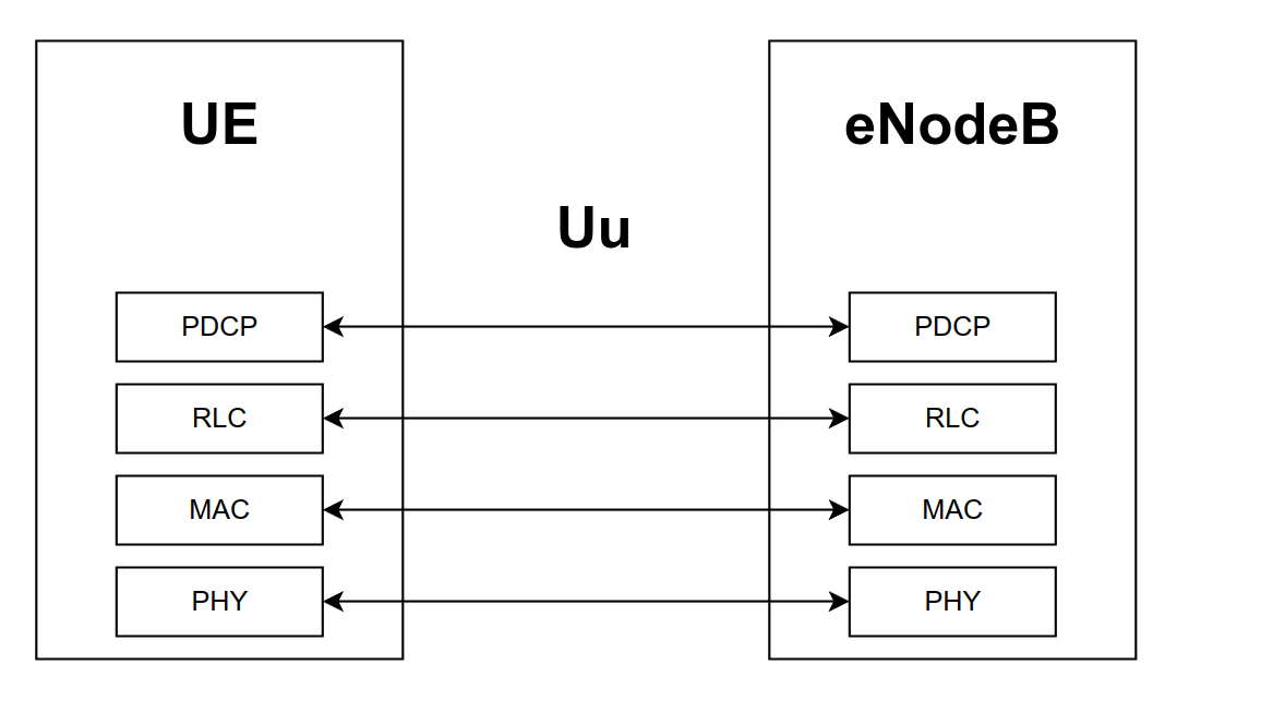
#UE <-> eNodeB
The first type is between the UE and the base station (eNodeB). The control radio interface between the UE and the eNodeB is called Uu. The protocol stack involved in this communication is shown below
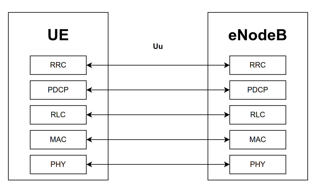
As we can see, at the top we see the RRC protocol, which is the high level protocol that is used between UE and eNodeB. Notice how RRC messages are wrapped in PDCP messages, which are wrapped in RLC messages, and so on until we arrive at the physical layer, where all the binary data is converted into radio signals and sent over the radio channel.
#eNodeB <-> MME
The second type is between the base station (eNodeB) and the MME, an internal component of the 4G core network (EPC). The control interface between eNodeB and MME is called S1-C. The protocol stack involved in this communication is shown below
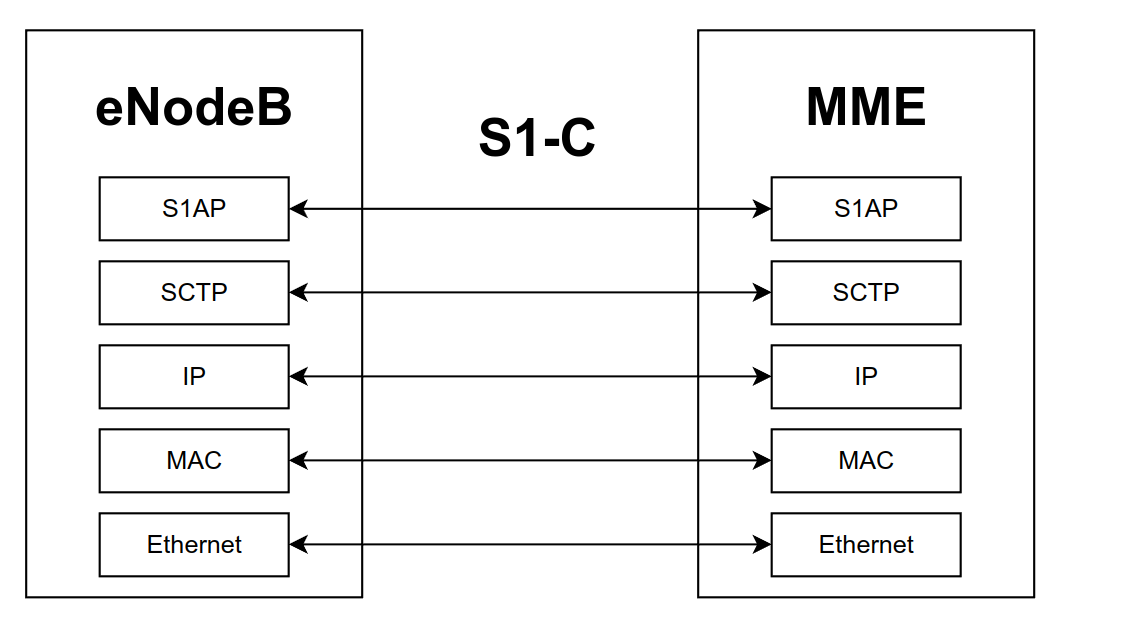
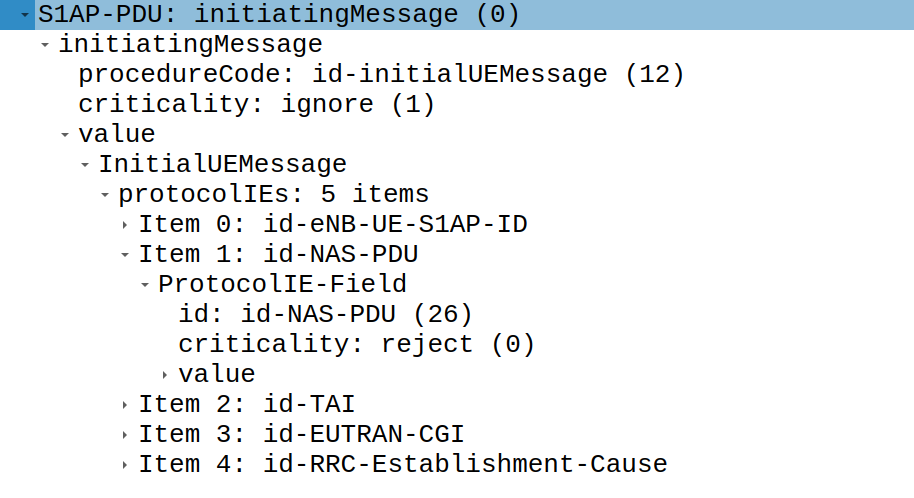
Notice how here the underlying communication mechanism is ethernet. This means data from the base station to the core network is carried through wire. On top of this, we find the well known IP protocol. In terms of the transport layer, instead of the TCP, used by internet, we find the SCTP, which is a message-oriented reliable transport protocol. On top of SCTP finally we find the S1AP protocol. S1AP messages can be used to carry NAS messages sent by the UE for the MME.
Consider for example the NAS attach request seen previously. This
attach request is wraped within a S1AP message. In particular it
is contained within the id-NAS-PDU item. Other data is contained
in the message to give the MME the correct context data.
#eNodeB <-> eNodeB
The third and final type of communication in the control plane is the communication that happens between different base stations. As I mentioned, there are many base stations in a 4G networks, and sometimes they need to communicate to exchange data regarding particular UE sessions. This happens for example during the handover procedure, which happens when the UE, moving around, starts to connect to a new base station. The control interface between eNodeB and eNodeB is called X2-C. The protocol stack involved in this communication is shown below
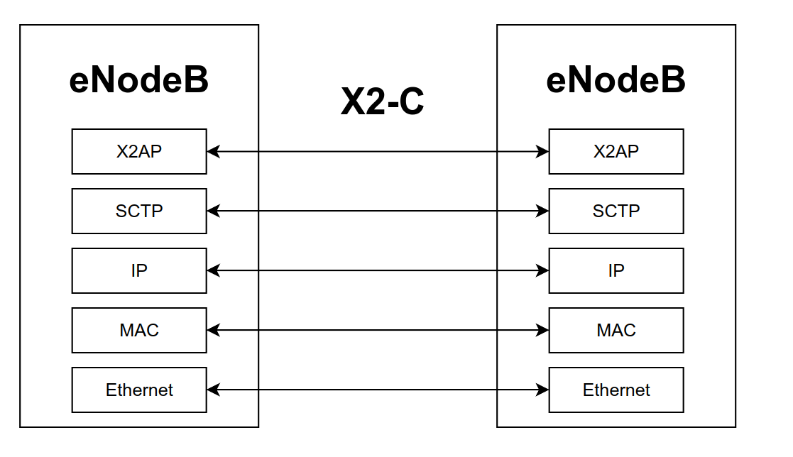
Notice how the communication between eNodeB and eNodeB is also done through Ethernet. I suppose because it can scale much better than a radio interface. The difference between this and the interface between eNodeB and MME is that the top level protocl here is the X2AP protocol instead of the S1AP protocol.
#User Plane
In the user plane (U-Plane) we find the following types of communication:
- UE \(\leftrightarrow\) eNodeB
- eNodeB \(\leftrightarrow\) MME
- eNodeB \(\leftrightarrow\) eNodeB
#UE <-> eNodeB
The first type is between the UE and the base station (eNodeB). The interface used is called Uu, and its the same interface used for the control plane. The protocol stack involved in this communication is shown below
Notice how the user plane between UE and eNodeB stops at the PDCP layer for the data packets, and not at the RRC layer, which is instead used in the control plane. Other than this change, the rest is similar to the control plane case.
#eNodeB <-> S-GW
The second type is between the eNodeB and the S-GW, a component of the 4G core network (EPC), also known as service gateway. The interface used is called S1-U. The protocol stack involved in this communication is shown below
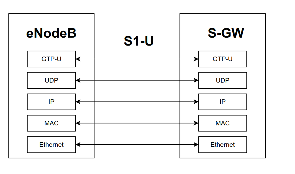
Notice how for user data packets, instead of using the reliable SCTP, the more frugal UDP is used. On the top level instead we see the GTP-U protocol, which is the one that carries the actual user data.
#eNodeB <-> eNodeB
Finally, the third and final type of user plane communication is between an eNodeB and another eNodeB. The interface used is called X2-U. The protocol stack involved in this communication is shown below
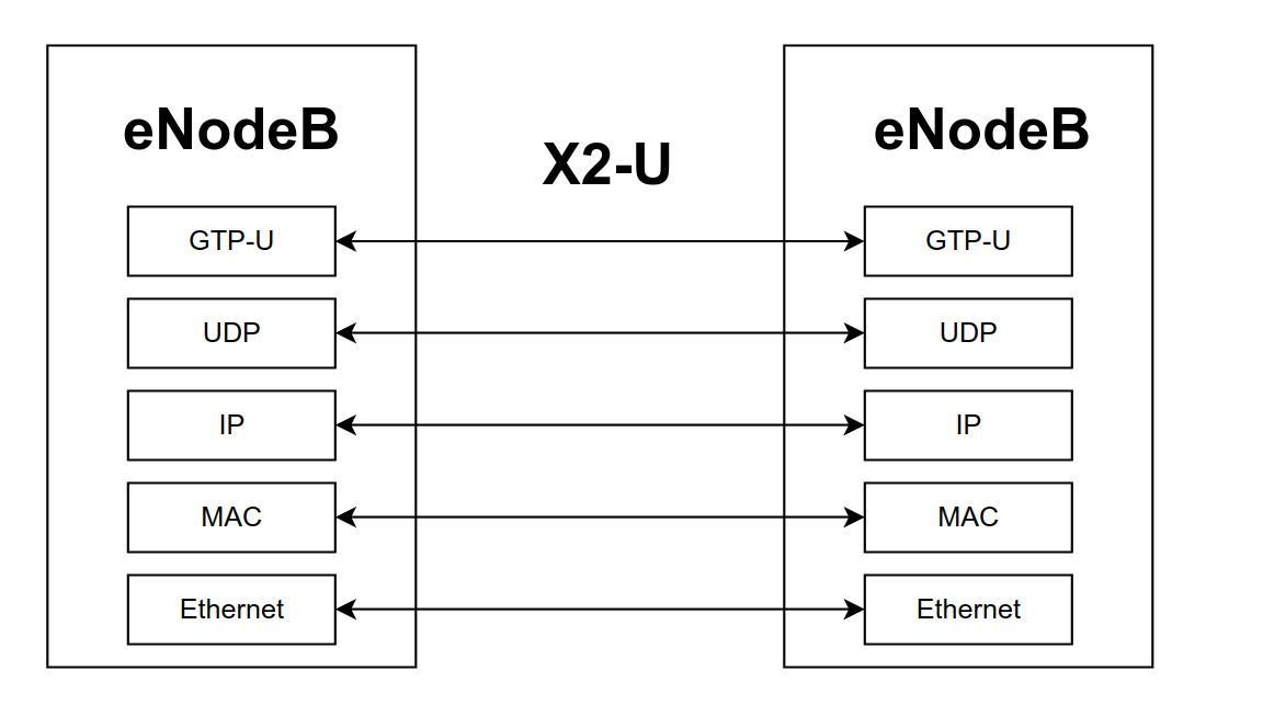
Here the stack is the same as the one used between eNodeB and S-GW, so there's not much to say.
#Sessions
So far I've mentioned many different protocols. What's important to remember however is that when learning a new subject, it is always crucial to understand the right level of detail one needs to have. While describing the 4G protocol stack is useful to construct a solid understand of 4G networks, we have to ask ourselves
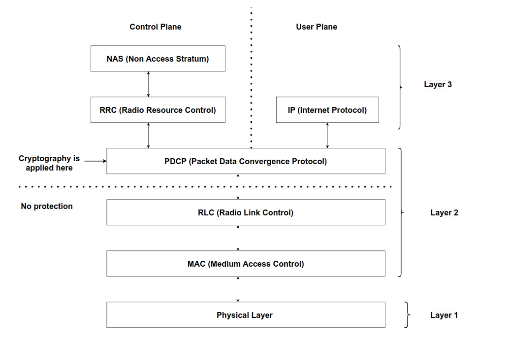
Out of the many different viewpoints, the one I'm interested in is the cryptography aspect of the communications, and in particular in the position that the UE plays. Choosing this particular viewpoint, I can abstract away, at least to some extent, details that have to do with radio interfaces and also with the connection between different components, such as how the eNodeB connects to the MME or the S-GW. I'm just interested in the sessions established starting from the UE. For example, out of the many protocols I've mentioned such as S1AP, X2AP, NAS, RRC, PDCP, RLC, etc.. what interest me is that cryptography is applied at the PDCP layer. This means that everything that is sent below that layer has no cryptography guarantees, while everything that is sent above that layer should be protected. Putting it all together, the viewpoint we should have about the protocol stack implemented in the UE should be the following one
Other questions that have to do with cryptography at the UE side are:
- How many communication sessions do we have?
- How are these sessions authenticated?
- How are these sessions protected?
- How are the secret keys of the protection of these sessions established?
Before finishing up, let's answer at least partially each one of these questions
#How many communication sessions do we have?
In terms of the number of sessions, we find two sessions in the control plane and one session in the user plane. In the control plane we have
-
NAS session (UE \(\leftrightarrow\) MME). The NAS session is established between the UE and the MME.
-
RRC session (UE \(\leftrightarrow\) eNodeB). The RRC session is established between the UE and the eNodeB.
In the user plane we have
- data session (UE \(\leftrightarrow\) eNodeB). The data session is established between UE and the eNodeB and carries general user plane data.
#How are these sessions authenticated?
In terms of authentication, all the sessions needed to make a 4G communication work are set up after a mutual authentication algorithm is executed between the UE and the EPC. The authentication assumes that both the UE as well as the EPC share a same long term secret \(k\). This is the secret that on the UE side is saved within the SIM card, and on the EPC side is saved within the HSS (Home Subscriber Service) database. The authentication procedure take places within the broader attach procedure, which is the first thing that happens when a UE asks to join a 4G network.
#How are these sessions protected?
There are two different types of protection, confidentiality protection, that makes sure that no one but the authenticated parties can see the actual data, and integrity protection, which makes sure that no one but the authenticated parties can generate valid data.
In 4G networks control plane sessions, which are the NAS and RRC sessions, are protected with both confidentiality and integrity. When it comes to user plane however only confidentiality is given, which means that
This means that an attacker can, potentially, change the encrypted payload containg user data and the receiver might not understand if something has been changed or not. This attack has actually been carried out over the DNS protocol, which by itself provides no integrity protection in a famous research done by Rupprecht et al., titled Breaking LTE on Layer Two.
When it comes to the specific algorithms, the standard describes four different encryption algorithms (to give confidentiality), and four different integrity algorithms (to give integrity).
The encryption algorithmns for protecting the control plane are specified by a particular string \(\text{EEA\{X\}}\), where
\[\text{EEA} \longrightarrow \text{EPS Encryption Algorithm}\]
The currently standardized algorithms are
| Identifier | Description |
|---|---|
| EEA0 | Null encryption |
| EEA1 | Based on SNOW-3G |
| EEA2 | Based on AES-CTR |
| EEA3 | ZUC |
For details on how these work, in the future I will write a specific blogpost and later I will link it here.
The integrity algorithms for protecting the control plane are also specified by a particular string \(\text{EIA\{X\}}\), where
\[\text{EIA} \longrightarrow \text{EPS Integrity Algorithm}\]
The currently standardized algorithms are
| Identifier | Description |
|---|---|
| EIA0 | Null integrity |
| EIA1 | Based on SNOW-3G |
| EIA2 | Based on AES-CMAC |
| EIA3 | ZUC |
For details on how these work, in the future I will write a specific blogpost and later I will link it here.
Finally, when it comes to the user plane, confidentiality is obtained through the usage of AES-CTR.
#How are the secret keys for these sessions established?
During the authentication procedure, an authentication vector is generated within the EPC core starting from the shared secret \(k\). This vector contains various values, some of them random, and some of them sequence number. Starting from these values, a hierarchy of keys can be computed by the various components involved in the communication (UE, MME, eNodeB).
All of this to say that there is a clear distinction between long term secrets and session secrets, which is a very good aspect of security, as it makes sure that a compromise of a single session does not transform into long term compromise of future sessions.
#Conclusion
So far there's still a lot of details that are missing. Some questions that one might still have at this stage are:
-
How does the attach procedure work in detail?
-
How does the mutual authentication work in detail?
-
How are the session keys generated?
-
How do the cryptographic primitives used to protect the confidentiality and integrity of the various sessions work in detail?
-
How are these cryptographic primitives actually initialized and used?
In future blogposts I will try to tackle, to the best of my ability, some of these questions.