Lately I've had a passive exposure to Digital Signaling Processing
(DPS) and Software Defined Radio (SDRs), as some of my colleagues
work with these technologies. Given my complete ignorance when it
comes to radio signals, I decided to take up the opportunity that
has been given to me to explore this new world. In this blog post I
want to explain the main structure of a 4G network, and how, with
some software and hardware, you can create your own personal 4G
network at home.
As for the structure of this blog post, I will first introduce the core architecture of a 4G network, then I'll describe all the hardware and software requirements needed to make your own network work, and finally I'll show step by step how to compile and execute each software in order to connect a real phone to a custom 4G network. Hope it's an interesting read that can shed some light into a fascinating area of technology!
DISCLAIMER: Given my lack of in depth knowledge when it comes to radio signals, anything I can mention could be not completely accurate. If you spot some errors feel free to correct me in the comments below.
#Structure of a 4G network
First of all, if you come from a background in networking, the first thing to understand is that much of what you know about networking in the digital realm remains very much relevant to the world of mobile, and in particular of 4G networks. The main idea of a 4G network is to combine together radio signals, on the one hand, with your typical digital network packets.
From a high level abstraction, a 4G network is made up of three main parts, which are described as follows:
-
User Equipment: This is the device of the end-user. This is the phone, or, in general, the end-device you use to connect to the network. The user equipment is able to send and transmit radio signals at particular frequencies.
-
Core Network: You can think of the core network as a sort of "cloud" in the context of mobile networks. Internally, the core network is made up of various components, which communicate with eachother in order to keeps track of the internal state of the mobile network, of the various UEs currently connected, of the various services that need to be given to the various UEs and many other things of the sort.
-
Base Station: Between the UE and the core network there's the third and final component, which is the base station. This is the station that communicates with the user equipment through the usage of radio signals. It is the bridge that connets a UE to a core network.
The following picture should make things clearer
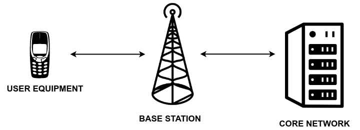
As we can see, the UE (User Equipment) is able to communicate with the core network by going through the base station. While the communication between UE and base station only consists of radio signals, the communication between base station and core network consists of both radio signals as well as the more traditional way of transmitting data through wires. This architecture makes a lot of sense, because radio signals give you flexibility of movement, something required by UEs, while wire communication allows you to have a more reliable and scalable way of transfering user data for long distances.
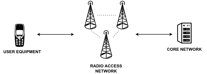
While in the demo at the end of this blog post I'll work with only a single base station, in real networks there are actually lots of base stations scattered across a given region of space, each one covering a particular area of interest. All these stations, taken together, form a particular radio access network, which in 4G is called the E-UTRAN. Whenever a user equipment goes out of the range of one base station, it can hopefully find another base station in order to keep the connection it has established with the core network.
In the world of telecomunications there are, sadly, lots of acronyms. Here I mention a really limited number of acronyms that can be found while studying 4G networks:
- UE: stands for "User Equipment"
- EPC: stands for "Evolved Packet Core", and its the name given the core network in 4G networks.
- eNodeB: stands for "Evolved Node B", and its the name given to the radio base station in 4G networks.
- E-UTRAN: stands for "Evolved Universal Terrestrial Radio Access Network", and represents the air interface for 4G networks.
The tragedy here is that these acronyms change between the various evolutions of the protocols. So, for example, the base station for 5G networks is called gNodeB instead of eNodeb, although conceptually it refers to the same component of the network. It sort of makes sense to have different names, since the technical specs are different. Still, the jargon is really heavy. I'll not mention much about 5G in this blog post, but it's something to keep in mind when trying to make sense of these domains.
Digging deeper into the architecture, the core network is actually made up of different internal components, each of which deals with a specific aspect of the network.
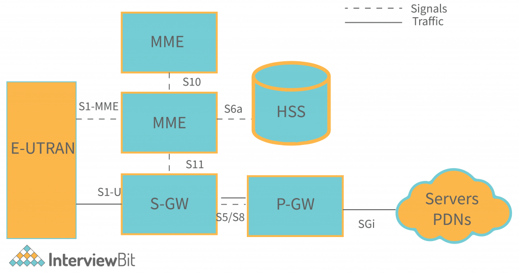
Below I give a brief description for the most important components that so far I myself have understood:
-
Mobility Management Entity (MME): The MME is the entry point of the network when it comes to the data control channel. The base stations that form the E-UTRAN network communicate with the MME for exchanging information on various topics such as security procuderes (UE authentication, confidentiality and integrity protection), as well as the basic session management between the UE and the core network.
-
Home Subscriber Server (HSS): This acts as the main subscriber database which provide details of the subscribers to the other components of the core network. This is used during the authentication procedure to generate the challenge vectors that are then sent to the UE. This challenge vectors are generated by knowing the secret key \(k\) that is also stored within the SIM of the UE.
-
Serving Gateway (SGW)
-
Packet Data Network Gateway (PGW)
-
Access Network Discovery and Selection Function (ANDSF)
-
Evolved Packet Data Gateway (eDPG)
When a User Equipment (UE) wants to connect to the network, first it finds a base station that supports the desired connection. Then, between the UE and the selected eNodeB, a radio channel is created, and within this radio channel the UE sends to the core network an attach request, which is used to initialize a particular authentication procedure that allows the core to correctly identify the UE that wants to join the network.
There are various protocols involved in this attach procedure. Some of these protocols have to do with the management of the radio channel between the UE and the base station and between the base station and the core. I have no idea how these protocols work in detail. There are also other protocols which I understand better, such as the cryptographic protocols that are used to perform authentication and to protect the data sent through confidentiality and integrity.
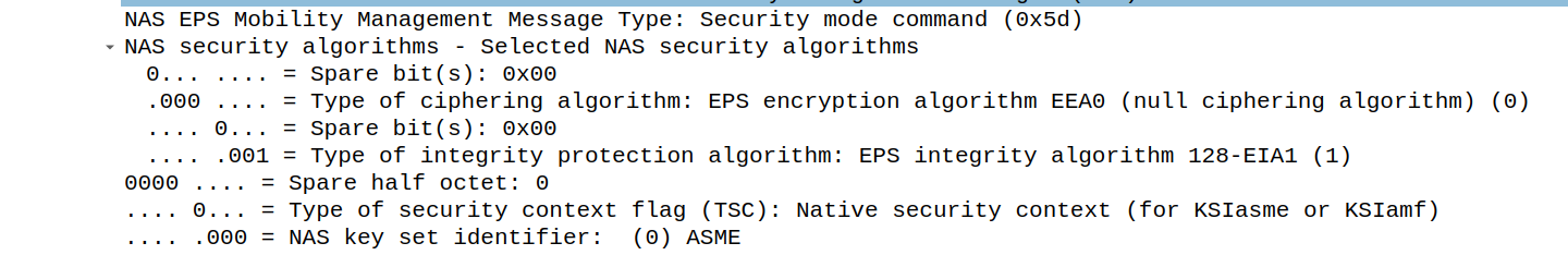
From a cryptographic point of view, the idea here is that before the UE even attempts at connecting to the core network, UE and CORE both share the same secret \(k\). This is the secret that is written into the SIM of the UE device and into the HSS component of the core network. By using this shared secret the core network is able to authenticate the UE device with a challenge-response protocol that only the device that knows the shared key \(k\) can correctly respond. Once authentication has been correctly completed, a series of keys are generated starting from the symmetric keys. These keys are used to protect the confidentiality and the integrity of various sessions that are established during the communication between the various components of the network. Some of these sessions involve the UE and the core network, while some other involve the UE and the base station. After cryptography has been taken care of, the core network starts to offer various services to the UE. These services depend on many factors. Some of these factors have to do with the capabilities offered by the particular UE. Below you can find some of these messages taken from a network trace of an attach request.
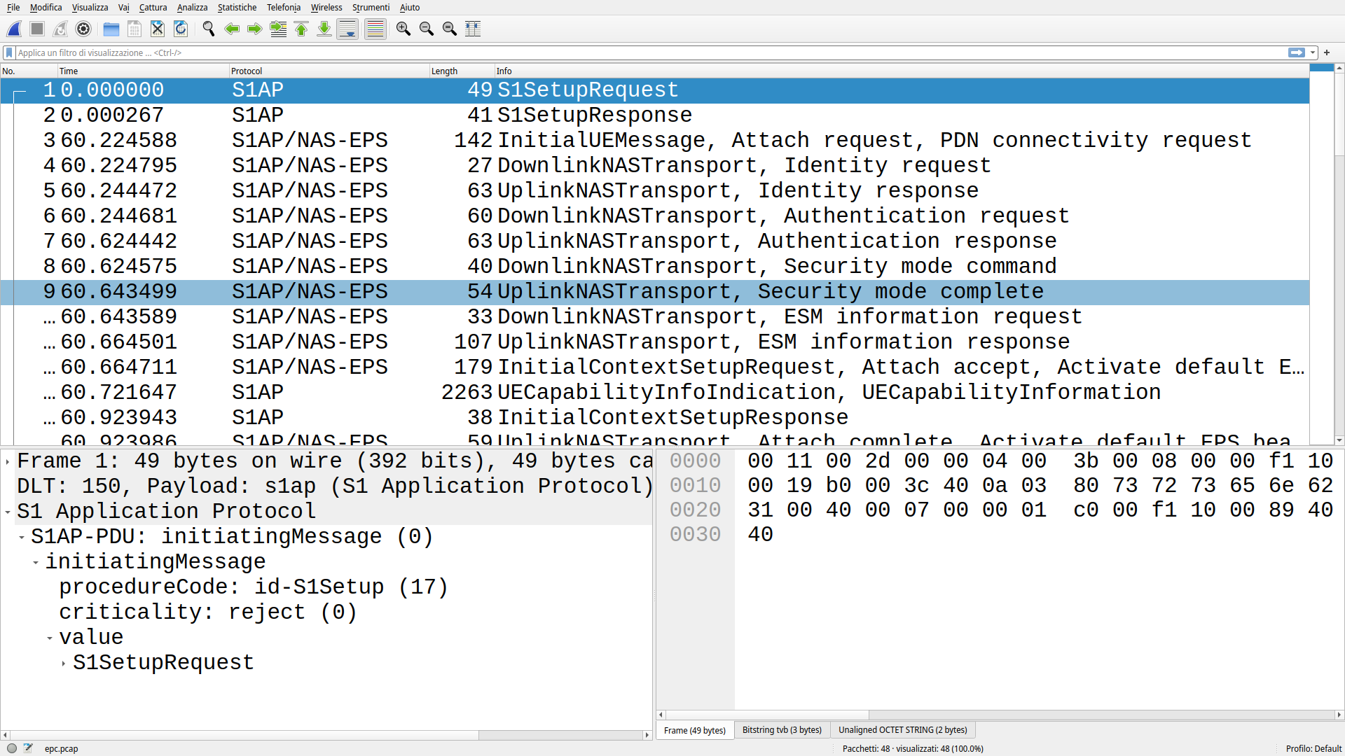
The authentication procedure here is wrapped within messages of the
NAS-EPS protocol, where NAS stands for Non-Access-Stratum and it is
one of the main protocol that is used between the UE and the core
network. In any authentication procedure we typically find the
following messages:
Attach Request,
Identity Request, Identity Response,
Authentication Request, Authentication Response,
Security mode command, Security mode complete
These messages are used to authenticate the user and to establish
the security context. Out of all these messages, the Identity request and Identity response are sent only the first time the UE
connects to the core network. These messages are critical because
they contain the IMSI, which is the unique identifier of the UE
within the network of an operator. For subsequent connections these
messages are not sent, and other temporary identifiers are instead
exchanged. The security mode command message establishes the
algorithms that will be used to protect the messages at the NAS
layer.
There is much more to say that I have not mentioned here. The protocol stack of mobile networks is quite complicated, because a lot of protocols are wrapped within messages of other protocols. Anyhow, we should now have a good enough picture of the main architecture and the various components of a 4G network.
We can now describe in detail all the requirements needed to create a custom 4G network using your own personal computer. In terms of requirements, we distinguish two main classes of requirements: hardware requirements and software requirements.
#Hardware requirements
In terms of hardware, the most important thing we need is a device that is able to send and receive specific radio signal. Lately Software Defined Radios (SDRs) have been very useful when working with radio signals, especially in research, as they allow to send and receive various types of radio signals with good performances. The cool thing about SDRs is that they are programmable through software. This means that with a given SDR we can program it to listen to wifi signal, or 4G signal, or 5G signal, or even other types of radio signals. I do not know the details, but this re-programmability feature is mostly obtained through the usage of Field Programmable Gate Arrays (FPGAs).
A friend of mine (Thanks Raffaele), also reminded me to mention the fact that not all SDRs are fit for this particular task. While they can be modified through software, the hardware of each SDR still has some limitations on how it can functions, or what kind of radio frequency it can transmit and receive. In general, SDRs can be characterized by various things, such as the ability to be full-duplex, meaning that it can send and receive radio signals at the same time. Below you can find a table with some characteristics of various SDRs.
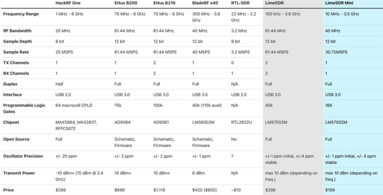
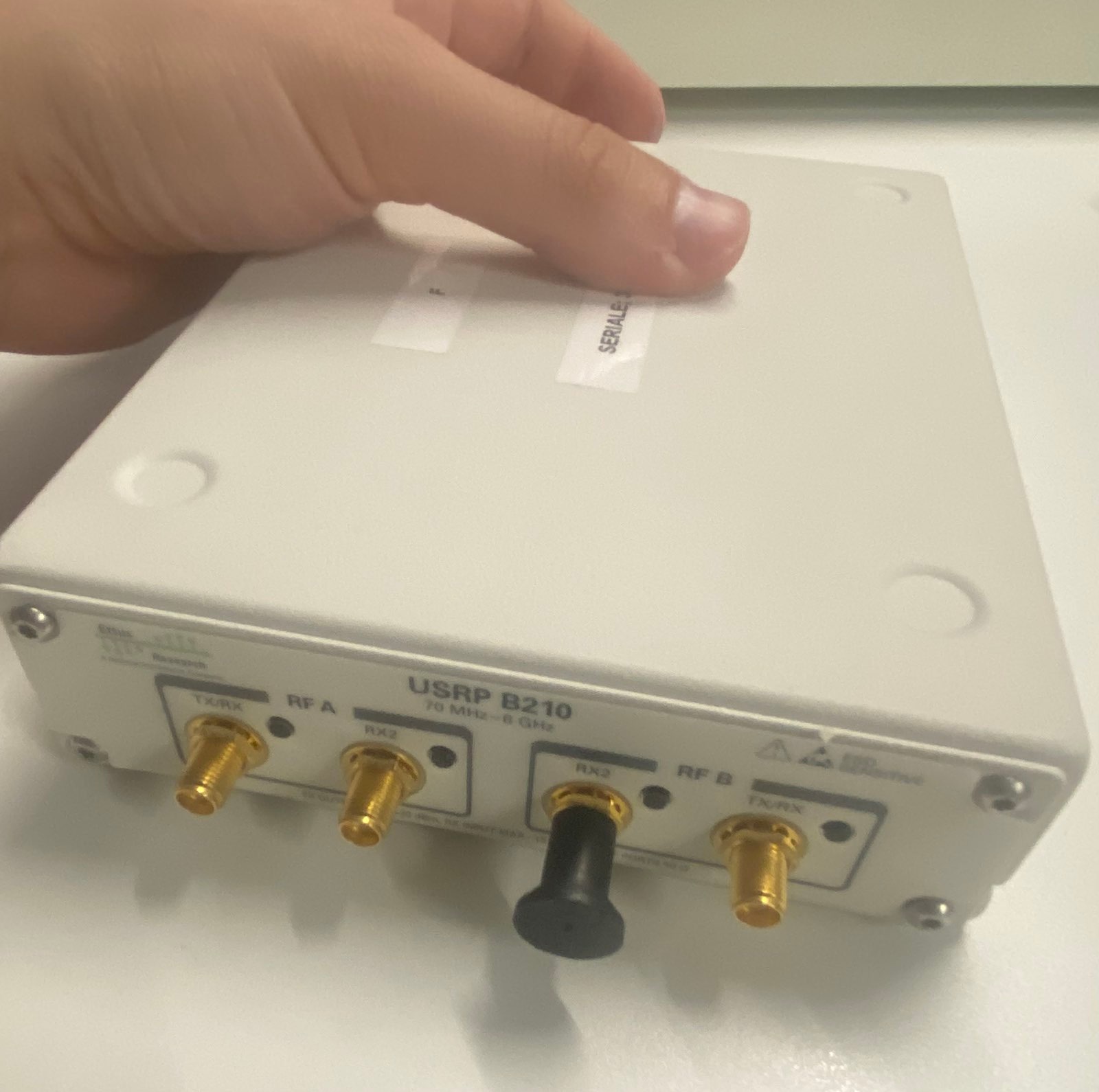
In this particular blog post I will use the USRP B210 developed by
Ettus, because that's something that was available in the lab I'm
working. This type of device allows to receive and send signals
with a frequency ranging from 70 MHz to 6 Ghz, a range that is
good for 4G networks, since they typically require between 450 MHz
and 3.8 Ghz. This device is also full-duplex, and this is why we
can easily use it to act as a base station in a 4G network. All in
all, it cosfts between 1.500€ and 2.000€. An image of the device is
given below
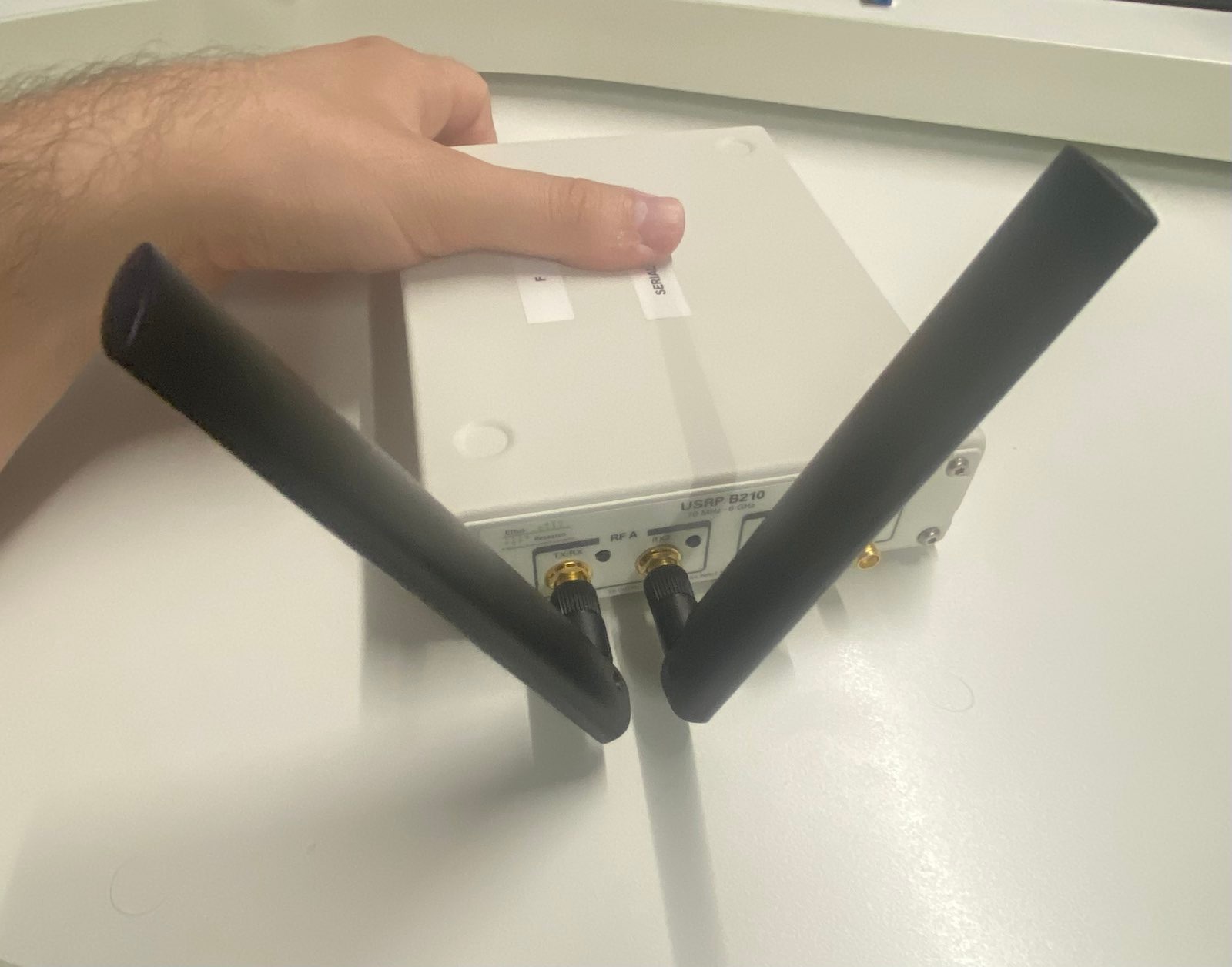
I think you can get a 4G network working also with cheaper options, maybe by buying two cheaper SDRs that are not full-duplex but that can handle only a single direction, and combining them through software to have a virtual full-duplex SDR. Other than the SDR itself we also need a couple of antennas to stick on the board. To be honest I don't know the particular model of these antennas. I should ask some of my colleagues. Anyways, here they are
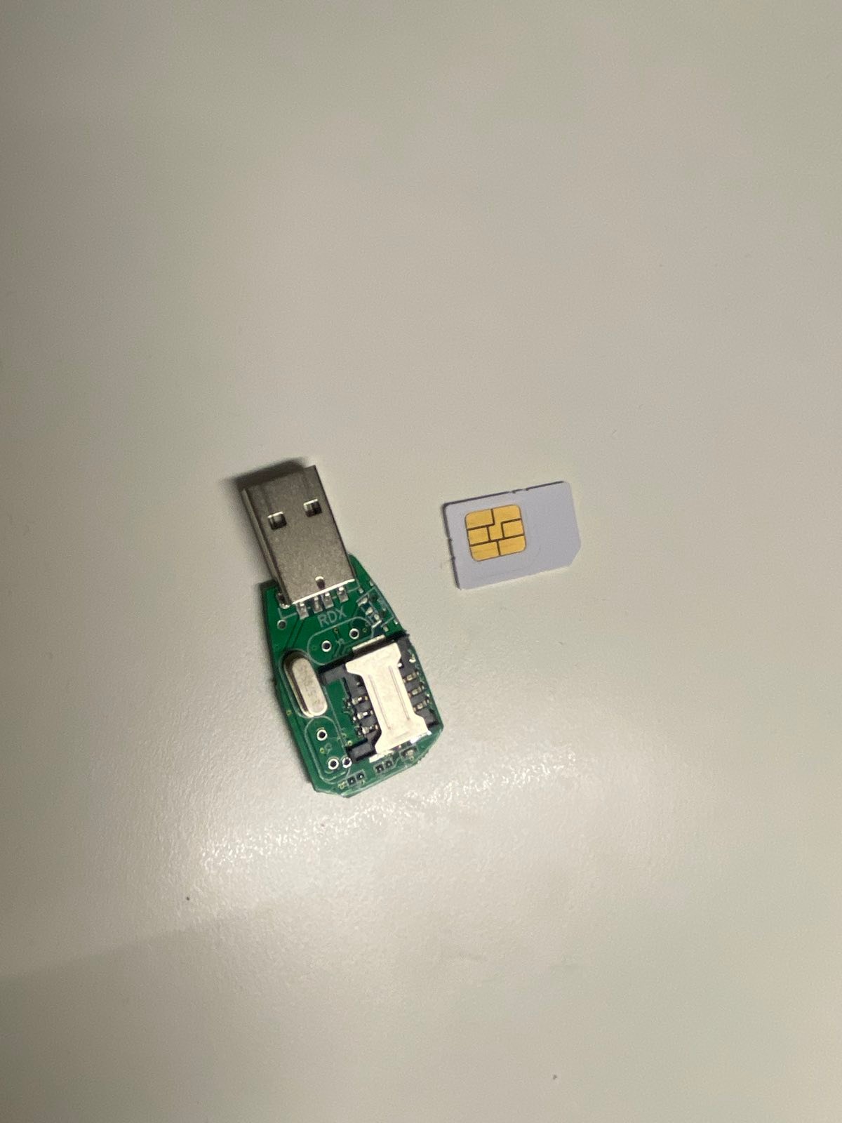
Continuing, other hardware requirements have to do with SIM related stuff. Specifically, if we want to use a custom SIM within our UE, we need to program the SIM to hold the custom data that will also be saved in the core network for enabling a correct authentication. This can be done with programmable 4G-SIM. I'm using the one from open-cells. There is also a device that is used to write custom data on the SIM.
Finally, the last thing we need is a smartphone. In terms of
smartphone, for this blog post I'll be using the one-plus-nord2-5g
model. Not all smartphones are the same for testing purposes
because some of them might reject the custom data we will write
into the SIM. For example, I've also tried to use an iPhone 11 pro
and an iPhone 6S, and to make them work with our testbed you have
to change two particular values which are called MCC, which stands
for "Mobile Country Code", and MNC, which stand for "Mobile
Network Code".
So, to recap, we have the following hardware requirements:
- Computer with linux
- SDR + Antenna
- Programmable SIM + Writer for SIM
- Smartphone
#Software requirements
In terms of software, we need mainly three different software: one for managing the SDR, one for writing custom data to the SIM, and one for managing the base station and the core network.
First things first, let us install all the relative dependencies
for all the software we need. These dependencies are to be
installed on an arch linux system. For other distributions you
have to find the relative packages.
pacman -S base-devel cmake mbdetls fftw boost lksctp-tools
pip install mako
#USRP Ettus SDR driver
The first software we need are the drivers that let us work with the SDR we have decided to use. Given that my SDR model is the Ettus B210, the respective drivers can be found in the following github repository: https://github.com/EttusResearch/uhd.
In this demo we will use version v.4.4.0.0.
git clone -b "v4.4.0.0" https://github.com/EttusResearch/uhd
To build it and install it execute the following commands
mkdir uhd/host/build
cd uhd/host/build
cmake ../ -DENABLE-DPDK=OFF
make -j$(nproc --ignore=1)
make install
After the installation is completed we execute ldconfig to update
the shared libraries, and we download all the available driver
images using the command uhd_images_downloader.
sudo ldconfig
sudo uhd_images_downloader
At this point we can connect the board to the computer in which
we installed the driver and we can obtained information about the
connected devices through the command uhd_find_devices. If the
command does not work by itself, I sugges to add the environment
variable LD_LIBRARY_PATH, and set it to the directory where there
shared object libuhd.so is installed.
$ sudo LD_LIBRARY_PATH=/usr/local/lib/ uhd_find_devices
[INFO] [UHD] linux; GNU C++ version 12.2.0; Boost_108100; UHD_4.4.0.main-0-753792a8
[INFO] [B200] Loading firmware image: /usr/local/share/uhd/images/usrp_b200_fw.hex...
--------------------------------------------------
-- UHD Device 0
--------------------------------------------------
Device Address:
    serial: XXXXXXX
    name: MyB210
    product: B210
    type: b200
As we can see, the UHD device is a B210 board. From the output I've omitted the serial number.
#Open Cells UICC/SIM programming
The second software we need is the one we will use to write custom data on our SIM. The software can be obtained from the Open Cells Project Website from the following command
$ curl https://open-cells.com/d5138782a8739209ec5760865b1e53b0/uicc-v3.2.tgz > /tmp/uicc-v3.2.tgz
Notice the version of the software is uicc-v3.2. By taking a
sha256sum we obtain the following hash
$ sha256sum uicc-v3.2.tgz
6425f05999ff3902e31419f4d94de38632871495a264ee4ad0879c1e20da3719  uicc-v3.2.tgz
we can open it using tar and compile it using make
$ tar -xvf uicc-v3.2.tgz
$ cd uicc-v3.2
$ make clean
$ make
we can then execute to see the various options
$ ./program_uicc --help
./program_uicc: unrecognized option '--help'
unrecognized option: 63
non-option ARGV-elements: Possible options are:
--port       Linux port to access the card reader (/dev/ttyUSB0)
--adm        The ADM code of the card (the master password)
--iccid      the UICC id to set
#srsRAN
The srsRAN project implements the majority of the code we will be using to have our custom 4G network. In particular, it implements a 4G core network as well as 4G base station. The software can be used with various SDRs, including the Ettus B210 model. The project is overall very interesting, and you can find more information regarding the srsRAN 4G project at the following link: https://docs.srsran.com/projects/4g/en/latest/index.html
We will use the release with tagged version 23.04 from the
official github repo.
curl -L https://github.com/srsran/srsRAN_4G/archive/refs/tags/release_23_04.tar.gz > /tmp/srsRAN_23_04.tar.gz
we can open the archive and build it as follows. This step has to be done AFTER we have compiled the uhd drivers.
cd /tmp
tar -xvf srsRAN_23_04.tar.gz
cd srsRAN_23_04
mkdir build
cd build
cmake ../
make -j$(nproc --ignore=1)
After compilation is over, in the build directory there should be
three directories, named respectively srsenb, srsepc and srsue,
each of which will contain an ELF binary that implements a
specific component of a 4G network. In particular we have:
-
./srsepc/src/srsepc, binary that implements the core network. -
./srsenb/src/srsenb, binary that implements the base station. -
./srsenb/src/srsue, binary that implements the UE.
To make sure everything has been built correctly we can perform the test by executing the following command in the build directory
make test
After this, the last thing we do is we install the software in the system by doing
make install
then we execute this last script to move the configuration files
in the ~/.config/srsran/ folder.
srsran_4g_install_configs.sh user
We are now ready to show how to use these software and hardware pieces to create a custom 4G network.
#Making it work
In order to create our custom 4G network we first have to write the UE credentials in two places: within the HSS component of the 4G core network, and within the SIM to be used by the UE.
In the user_db.csv file, present in the configuration directory of
the core, which is to be found in ~/.config/srsran/, we write
the following
#
# .csv to store UE's information in HSS
# Kept in the following format: "Name,Auth,IMSI,Key,OP_Type,OP/OPc,AMF,SQN,QCI,IP_alloc"
#
# Name:     Human readable name to help distinguish UE's. Ignored by the HSS
# Auth:     Authentication algorithm used by the UE. Valid algorithms are XOR
#           (xor) and MILENAGE (mil)
# IMSI:     UE's IMSI value
# Key:      UE's key, where other keys are derived from. Stored in hexadecimal
# OP_Type:  Operator's code type, either OP or OPc
# OP/OPc:   Operator Code/Cyphered Operator Code, stored in hexadecimal
# AMF:      Authentication management field, stored in hexadecimal
# SQN:      UE's Sequence number for freshness of the authentication
# QCI:      QoS Class Identifier for the UE's default bearer.
# IP_alloc: IP allocation stratagy for the SPGW.
#           With 'dynamic' the SPGW will automatically allocate IPs
#           With a valid IPv4 (e.g. '172.16.0.2') the UE will have a statically assigned IP.
#
# Note: Lines starting by '#' are ignored and will be overwritten
ue2,mil,001010123456780,00112233445566778899aabbccddeeff,opc,63bfa50ee6523365ff14c1f45f88737d,8000,0000000014a9,7,dynamic
ue1,xor,001010123456789,00112233445566778899aabbccddeeff,opc,63bfa50ee6523365ff14c1f45f88737d,9001,000000001234,7,dynamic
The data here contains various information about the UE that can
correctly authenticate to our custom 4G network. I don't know the
meaning of all these fields, but the second value, which is mil in
the first row and xor in the second, is used to specify the
algorithms to be used during the challenges in the authentication
procedure. Then we find the IMSI, which is sort of a unique
identifier for the UE. Then we have the key, which is the
symmetric key shared by the UE and the core.
Notice here that the IMSI value actually represents three
different things. The first three digits represent the MCC, then
there are two or three digits for the MNC, and the remaining is
actually the MSIN.
MCC  -> Mobile Country Code
MNC  -> Mobile Network Code
MSIN -> Mobile Subscription Identification Number
The next step is to write the same IMSI value as well as the same key into the SIM that will be inserted in the UE. Before executing this command we have to insert the SIM writer into the computer.
The command is then the following one. Notice that the adm value
is specific to the SIM and its written on top of the SIM. In the
command I have omitted the specific value that I used.
sudo ./program_uicc --adm XXXXXXXX --imsi 001010123456780 --acc 0001 --key 00112233445566778899aabbccddeeff --opc 63bfa50ee6523365ff14c1f45f88737d -spn "Test" --authenticate --noreadafter
We should see an output similar to this one
Existing values in USIM
ICCID: 89860061100000000150
WARNING: iccid luhn encoding of last digit not done
USIM IMSI: 001010123456780
USIM MSISDN: 00000001
USIM Service Provider Name: Test

Setting new values
Succeeded to authentify with SQN: 5280
set HSS SQN value as: 5312
...
After we write to it we can read the contents by executing
sudo ./program_uicc
and we get
Existing values in USIM
ICCID: 89860061100000000151
WARNING: iccid luhn encoding of last digit not done
USIM IMSI: 001010123456780
USIM MSISDN: 00000151
USIM Service Provider Name: open cells

No ADM code of 8 figures, can't program the UICC
Once we do that we can insert the SIM into the UE.
Continuing, we mount the antenna on the SDR and connect the SDR to the computer through the USB cable.
Once this is done we can check if the computer sees the correct
SDR by executing uhd_find_devices
$ sudo LD_LIBRARY_PATH=/usr/local/lib/ uhd_find_devices
[INFO] [UHD] linux; GNU C++ version 12.2.0; Boost_108100; UHD_4.4.0.main-0-753792a8
--------------------------------------------------
-- UHD Device 0
--------------------------------------------------
Device Address:
serial: XXXXX
name: MyB210
product: B210
type: b200
At this point we can execute the core network and the base
station. Before executing the components we check the config files
to change a few lines. In the config file of the core, which is
the file /root/.config/srsran/epc.conf we change the apn value
from srsapn to interent under the [mme] section. This is to allow
the UE to use the internet by going through the core. Depending on
the IMSI we decided to use, we might also have to change the mcc
and mnc values. For example, when testing the iPhone 6S
connectivity I had to change mcc=222 and mnc=06.
[mme]
mme_code = 0x1a
mme_group = 0x0001
tac = 0x0007
mcc = 001
mnc = 01
mme_bind_addr = 127.0.1.100
apn = internet
dns_addr = 8.8.8.8
encryption_algo = EEA0
integrity_algo = EIA1
paging_timer = 2
request_imeisv = false
lac = 0x0006
We can also, optionally, enable the pcap option in order to save
the traffic that core receives into a pcap file. This is to be
found in the [pcap] section.
[pcap]
enable   = true
filename = /tmp/epc.pcap
Once these changes have been made, we can execute the core with the command srsepc
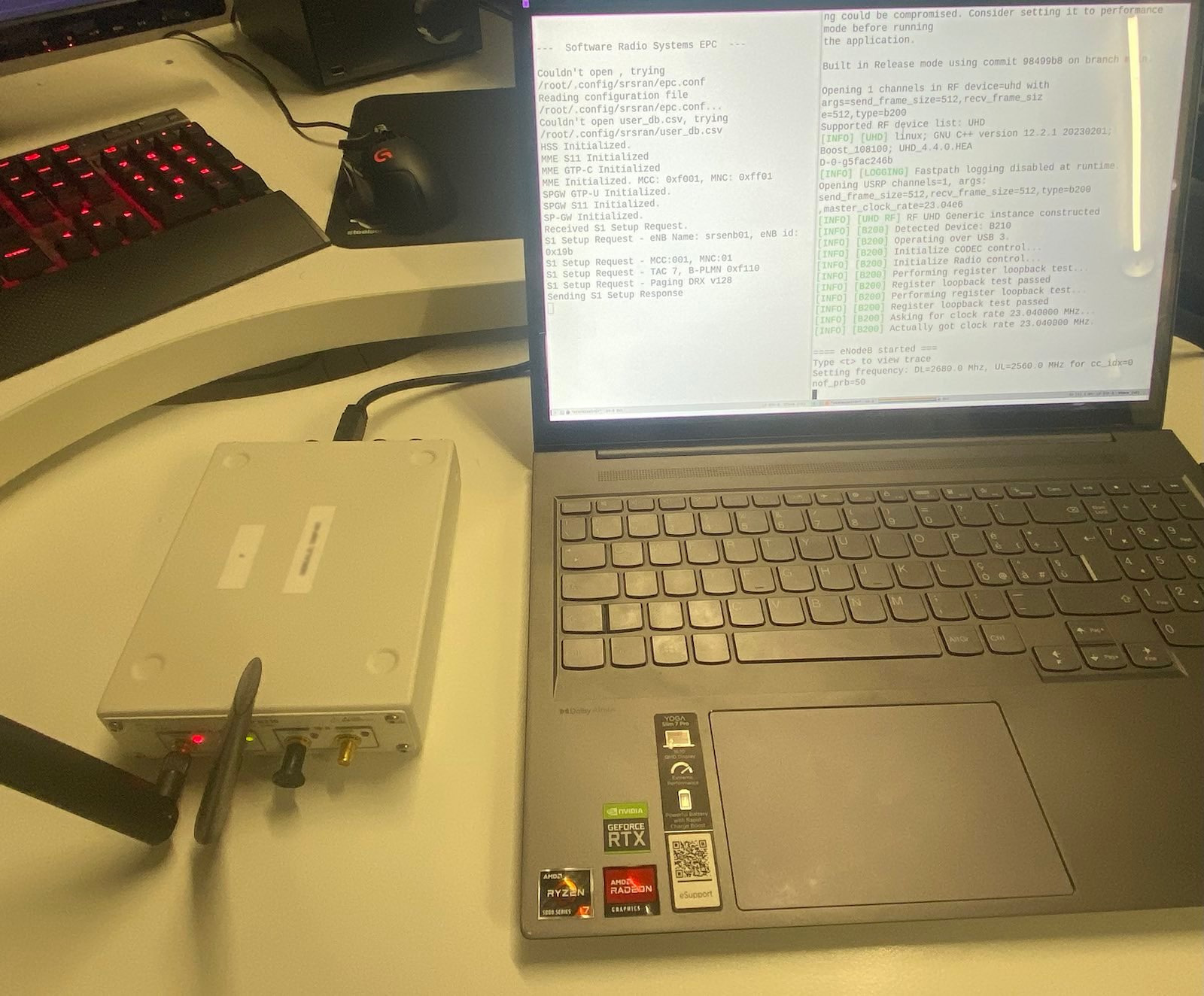
$ srsepc
we should see the following output, which indicates that the various components of the core have been correctly initialized.
Built in Release mode using commit 98499b8 on branch main.


---  Software Radio Systems EPC  ---

Couldn't open , trying /root/.config/srsran/epc.conf
Reading configuration file /root/.config/srsran/epc.conf...
Couldn't open user_db.csv, trying /root/.config/srsran/user_db.csv
HSS Initialized.
MME S11 Initialized
MME GTP-C Initialized
MME Initialized. MCC: 0xf001, MNC: 0xff01
SPGW GTP-U Initialized.
SPGW S11 Initialized.
SP-GW Initialized.
The last component to enable is the base station. First change the
configuration file of the base station, which is to be found in
the file ~/.srsran/config/enb.conf. We change in particular
the section [rf], where we change the device_name value from auto
to uhd as well as the device_args value from auto to
send_frame_size=512,recv_frame_size=512,type=b200. At the end we
will have the following
[rf]
#dl_earfcn = 3350
tx_gain = 80
rx_gain = 40

device_name = uhd

# For best performance in 2x2 MIMO and >= 15 MHz use the following device_args settings:
#     USRP B210: num_recv_frames=64,num_send_frames=64
#     And for 75 PRBs, also append ",master_clock_rate=15.36e6" to the device args

# For best performance when BW<5 MHz (25 PRB), use the following device_args settings:
#     USRP B210: send_frame_size=512,recv_frame_size=512

device_args = send_frame_size=512,recv_frame_size=512,type=b200
Once the configuration is done, we can execute the base station
with srsenb
srsenb
and we get the following
Active RF plugins: libsrsran_rf_uhd.so libsrsran_rf_zmq.so
Inactive RF plugins:
---  Software Radio Systems LTE eNodeB  ---

Couldn't open , trying /root/.config/srsran/enb.conf
Reading configuration file /root/.config/srsran/enb.conf...
Couldn't open sib.conf, trying /root/.config/srsran/sib.conf
Couldn't open rr.conf, trying /root/.config/srsran/rr.conf
Couldn't open rb.conf, trying /root/.config/srsran/rb.conf
WARNING: cpu0 scaling governor is not set to performance mode. Realtime processing could be compromised. Consider setting it to performance mode before running the application.

Built in Release mode using commit 98499b8 on branch main.

Opening 1 channels in RF device=uhd with args=send_frame_size=512,recv_frame_size=512,type=b200
Supported RF device list: UHD zmq file
[INFO] [UHD] linux; GNU C++ version 12.2.0; Boost_108100; UHD_4.4.0.main-0-753792a8
[INFO] [LOGGING] Fastpath logging disabled at runtime.
Opening USRP channels=1, args: send_frame_size=512,recv_frame_size=512,type=b200,master_clock_rate=23.04e6
[INFO] [UHD RF] RF UHD Generic instance constructed
[INFO] [B200] Detected Device: B210
[INFO] [B200] Loading FPGA image: /usr/local/share/uhd/images/usrp_b210_fpga.bin...
[INFO] [B200] Operating over USB 2.
[INFO] [B200] Detecting internal GPSDO....
[INFO] [GPS] No GPSDO found
[WARNING] [B200] The recv_frame_size must be a multiple of 8 bytes and not a multiple of 512 bytes.  Requested recv_frame_size of 512 coerced to 520.
[INFO] [B200] Initialize CODEC control...
[INFO] [B200] Initialize Radio control...
[INFO] [B200] Performing register loopback test...
[INFO] [B200] Register loopback test passed
[INFO] [B200] Performing register loopback test...
[INFO] [B200] Register loopback test passed
[INFO] [B200] Asking for clock rate 23.040000 MHz...
[INFO] [B200] Actually got clock rate 23.040000 MHz.

==== eNodeB started ===
Type <t> to view trace
Setting frequency: DL=2680.0 Mhz, UL=2560.0 MHz for cc_idx=0 nof_prb=50
[INFO] [UHD RF] Tx while waiting for EOB, timed out... 1.73016 >= 0. Starting new burst...
Notice the warning telling us to put the scaling governor of cpu0
to performance mode. This has to do for performance reasons, and I
shall not do it for this particular test. For more information I
suggest to look into it in the following URL: wiki.archlinux.org -
CPU frequency scaling.
After we have started the base station, if we then look at the output from the core process, we should see the base station attaching to the core
Received S1 Setup Request.
S1 Setup Request - eNB Name: srsenb01, eNB id: 0x19b
S1 Setup Request - MCC:001, MNC:01
S1 Setup Request - TAC 7, B-PLMN 0xf110
S1 Setup Request - Paging DRX v128
Sending S1 Setup Response
...
At this point the base station has started to work and send
signals. The only thing that remain is to power on the UE and
attach it to the network. With respect to the UE configuration, we
just have to remember to put the SIM with our custom
authentication data inside the UE. We also need to set within the
UE an APN with the type value set to internet.
As soon as we activate the SIM, we should see the core output as well as the base station output activate.
From the output of the base station we see
RACH:  tti=851, cc=0, pci=1, preamble=29, offset=0, temp_crnti=0x46
User 0x46 connected
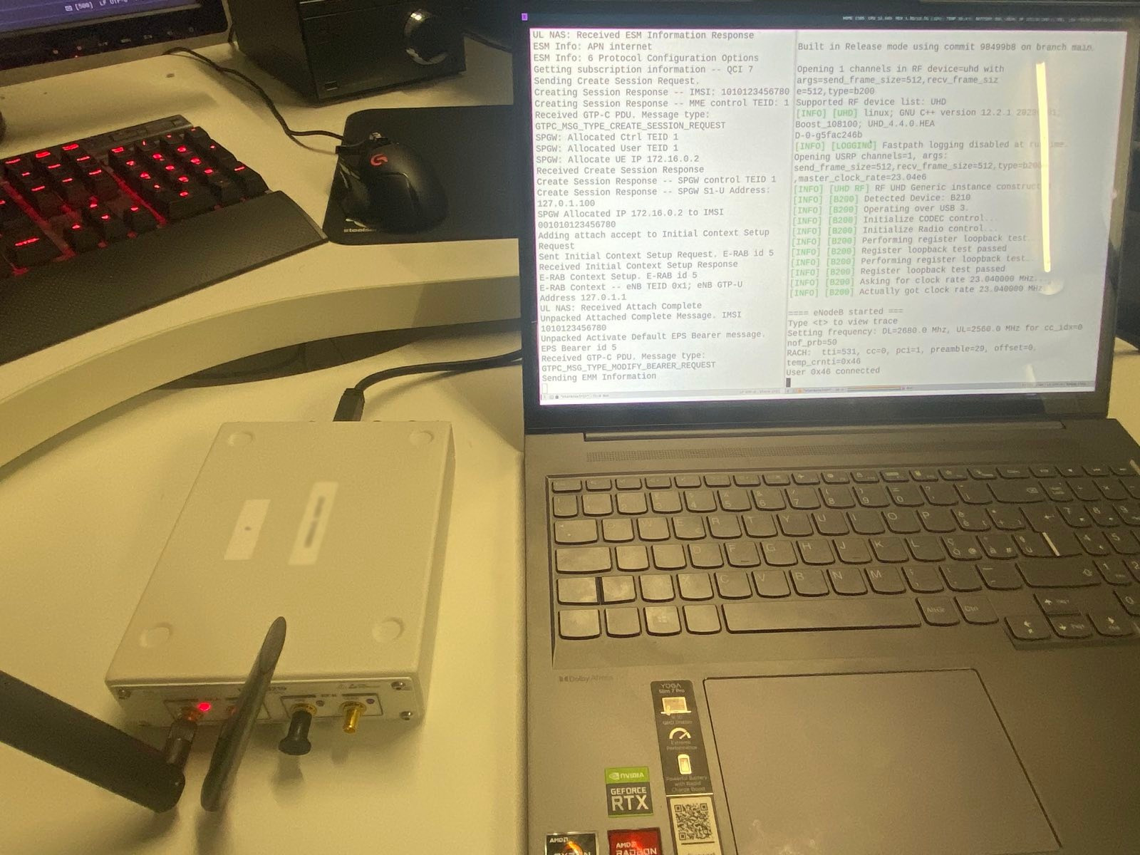
From the output of the core network we see the attach request of
the UE, the authentication procedure and a bunch of other things
that happen during the initial attachment. Notice how it printed
our custom IMSI, which is 001010123456780.
Initial UE message: LIBLTE_MME_MSG_TYPE_ATTACH_REQUEST
Received Initial UE message -- Attach Request
Attach request -- IMSI: 001010123456780
Attach request -- eNB-UE S1AP Id: 1
Attach request -- Attach type: 2
Attach Request -- UE Network Capabilities EEA: 11110000
Attach Request -- UE Network Capabilities EIA: 11110000
Attach Request -- MS Network Capabilities Present: true
PDN Connectivity Request -- EPS Bearer Identity requested: 0
PDN Connectivity Request -- Procedure Transaction Id: 23
PDN Connectivity Request -- ESM Information Transfer requested: true
Downlink NAS: Sending Authentication Request
UL NAS: Received Authentication Response
Authentication Response -- IMSI 001010123456780
UE Authentication Accepted.
Generating KeNB with UL NAS COUNT: 0
Downlink NAS: Sending NAS Security Mode Command.
UL NAS: Received Security Mode Complete
Security Mode Command Complete -- IMSI: 001010123456780
Sending ESM information request
UL NAS: Received ESM Information Response
ESM Info: APN internet
ESM Info: 6 Protocol Configuration Options
Getting subscription information -- QCI 7
Sending Create Session Request.
Creating Session Response -- IMSI: 1010123456780
Creating Session Response -- MME control TEID: 1
Received GTP-C PDU. Message type: GTPC_MSG_TYPE_CREATE_SESSION_REQUEST
SPGW: Allocated Ctrl TEID 1
SPGW: Allocated User TEID 1
SPGW: Allocate UE IP 172.16.0.2
Received Create Session Response
Create Session Response -- SPGW control TEID 1
Create Session Response -- SPGW S1-U Address: 127.0.1.100
SPGW Allocated IP 172.16.0.2 to IMSI 001010123456780
Adding attach accept to Initial Context Setup Request
Sent Initial Context Setup Request. E-RAB id 5
Received Initial Context Setup Response
E-RAB Context Setup. E-RAB id 5
E-RAB Context -- eNB TEID 0x1; eNB GTP-U Address 127.0.1.1
UL NAS: Received Attach Complete
Unpacked Attached Complete Message. IMSI 1010123456780
Unpacked Activate Default EPS Bearer message. EPS Bearer id 5
Received GTP-C PDU. Message type: GTPC_MSG_TYPE_MODIFY_BEARER_REQUEST
Sending EMM Information
At this point if we try to go to the internet with the phone, we
will not be able to. This is because to enable internet
connectivity we have to go back to the main folder in which we
installed srsran and execute the following script, where here
wlan0 is the name of the interface that gives internet to the
computer that hosts the core network. With this command the UE
will be able to connect to the internet by using the core's
computer network.
sudo ./srsepc/srsepc_if_masq.sh wlan0
And that's it, we have our own custom 4G network! We can browse the internet and... well, for now just that. We can also change the name of the network that is shown in the phone.
#Potential problems
While I was writing this blog post I made the same setup on two
different machine: the laptop that I use for work, and the desktop
computer I have at home. While in the laptop I had some problems
related to the setting of APNs within the cellphone, after fixing
these small issues everything worked fine and reliably. With the
desktop setup however things turned out quite problematic, and I've
yet to figure out what does not work properly. I suspect at this
point that the problem is related to the old hardware that runs on
my desktop, not sure if the processor or the motherboard itself,
because whenever I try to connect the UE to the base station, I get
nothing, not even an attempt, just nothing, the base station reads
nothing.
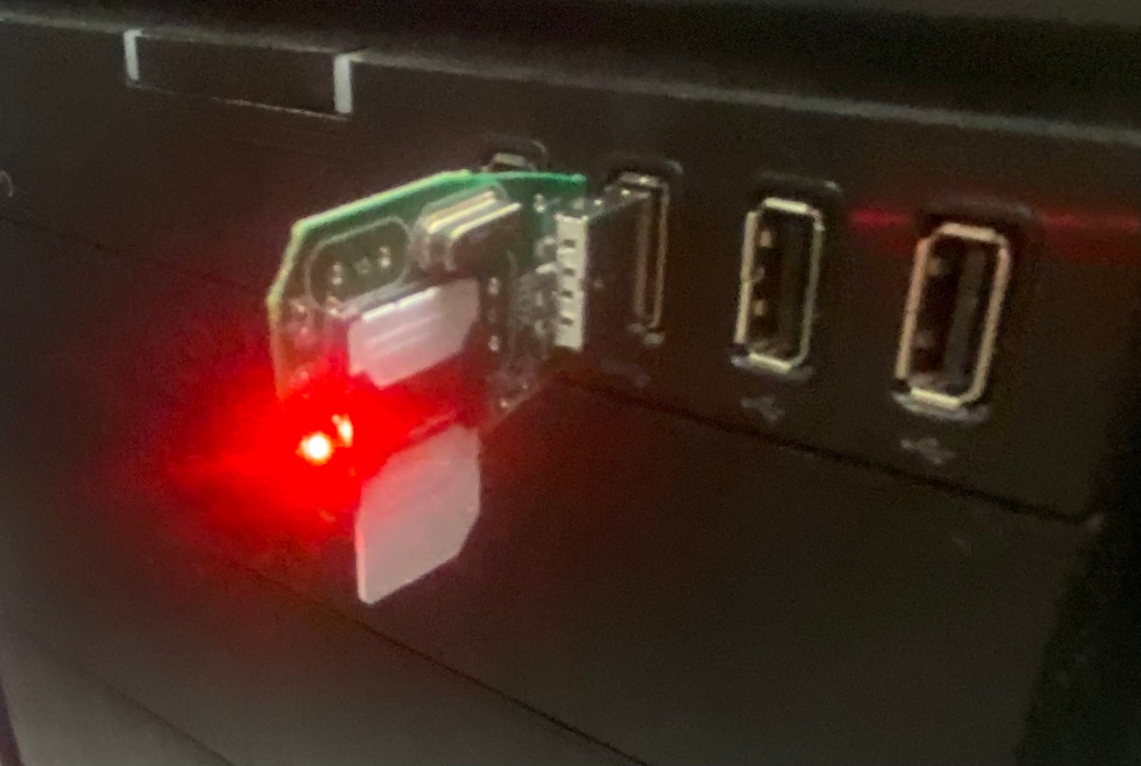
The only difference I've noticed between the two setup is that when
I connect the SDR to my laptop, there is a red and green light,
where the red lights up the TX/RX port, while the green light
lights up the RX2 port. When I connect the SDR to the desktop
however while the green like remains the same, the red light is
much weaker and barely lights up. Having said that, I'm pretty
ignorant when it comes to radio signal, so at this moment I'm not
able to debug this particular problem. Could this difference mean
something?
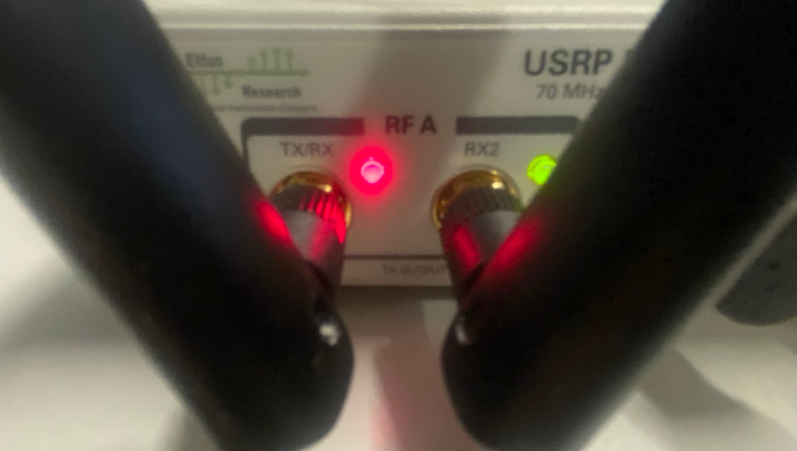
UPDATE 1: A colleague told me that this behavior might have to do with power issues, meaning that when the red light doesn't blink that much its because it doesn't receive enough power through the USB port. This devices have also an external power plug, but sometimes the USB cable is enough. It appears that in my desktop not enough power goes through the USB cable, and therefore I have this sort of problems.
UPDATE 2: I actually tried to power it up with an external power plug, and the problem remains. Now I suspect it has to do with the fact that the USB ports in my desktop are really slow, and they're not as fast as the SDR requires them to be.
#Possible extensions
We have created our own custom 4G network that allows a basic UE to
connect to the core network. With this we can grant internet to the
UE by using the internet connection of the core network. There are,
however, a whole lot of things that can be improved. Just to
mention one, for example, this custom 4G network does not support
calls with VoLTE. There are other things like this that can be
extended, most of which I do not even know. This is just to point
out the obvious: this setup is just a very limited 4G testbed.
#What about 5G?
To finish this long blog post, let us now wonder: and what about 5G
then? What does it change from 5G to 4G?
As I repeated multiple times, I'm no expert in this. However, from the little I understand, one can view the 5G network architecture as an extension of the 4G network architecture. The basic building blocks remain still the UE, the base station and the core network, but in 5G the core network is much more complex and offers advanced services such as 5G network slicing. At the same time, the UE and the base station have also changed to offer even greater speeds and reliability.
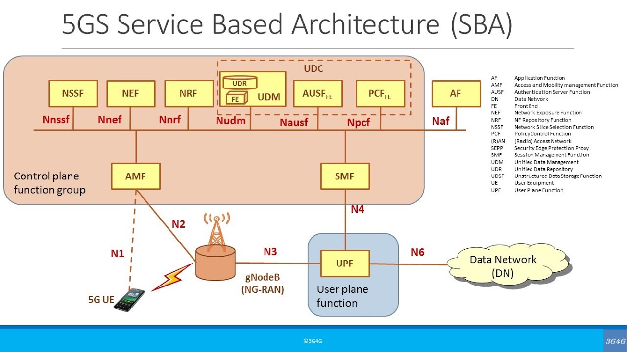
The core network portion of the 5G network is very similar to a
traditional cloud, and different components communicate with
eachothers using HTTP REST APIs protected through TLS. This
structure is called the Service Based Architecture (SBA).
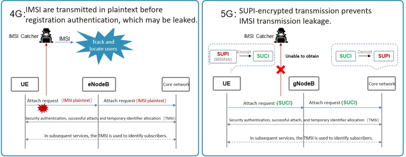
There many other changes going from 4G to 5G. Another change that I do know about is that in 4G the IMSI is sent in clear the first time the UE connects to the network. This privacy gap has allowed for the development so-called IMSI-catcher, which are malicious devices that act as 4G base stations and force UEs to connect to them in order to steal their IMSI. In 5G this gap has been closed, by protecting the IMSI with encryption even in the first attach request. The way in which this is actually implemented are very complicated, and have to do with special SIMs called eSIMs. Anyways, this blog post is already too long.
#References
That's it. I hope it was an interesting read. In future blog posts, maybe, I can also write in more detail about the 4G authentication flow with more cryptographic detail, which is something I understand much better than, say, the procedure used by the UE to establish the radio channel with the base station. Having said that, it would be also cool to understand a little bit better how Digital Signaling Processing actually works under the hood.
Some useful references for understanding more about 4G and 5G
- https://github.com/srsran/srsRAN_4G
- https://github.com/EttusResearch/uhd
- https://docs.srsran.com/projects/4g/en/latest/general/source/1_installation.html
- https://open-cells.com/index.php/uiccsim-programing/
- https://www.youtube.com/watch?v=LotQ1RwXdoE
- https://moniem-tech.com/questions/what-is-the-difference-between-4g-and-5g-identity-security/
- https://www.youtube.com/watch?v=4JXhKhxY3Oo&list=PLgQvzsPaZX_ZAaohgRhpb_dv7RL1fNZB5
- https://www.crowdsupply.com/lime-micro/limesdr-mini-2