For my high-school final work I read about Turing's life. I read about his computational model, now known as turing machine, and of the help he gave to the Allies for the decryption of german comunications during World War II (1939-1945). You can read my final artifact at the following URL, although I must warn you that it is written in the italian language
https://archive.leonardotamiano.xyz/education/high_school/thesis/
In the thesis I also give a high level overview on the functioning of the enigma machine.
I worked on that in 2015. Now its 2023, which means that 8 years
have passed since that day. In these long years, I have learned
quite a few things related to computer science and programming. As
a little side-project, I have decided to go back and look at the
enigma machine, but this time, I will not limit myself to give a
high level overview. I will instead implement every component of
the machine using the C programming language in order to obtain a
fully functional emulator of Enigma capable of encrypting and
decrypting messages as the germans did back in the days.
In this blog post I describe in detail the implementation. You can find the final code in the following repository
https://github.com/LeonardoE95/enigma-machine
If you find any mistake, or something that makes my implementation diverge from the original functioning of the machine, please let me know, either in the comments below or in github itself.
Hope it is an enjoyable read!
#On Substitution Ciphers
Before even starting with Enigma, it is important to briefly remind ourselves what is a substitution cipher. This is because, in its essence, the Enigma machine is the implementation of a very, very complex substitution cipher.
Now, consider the characters of the english alphabet
\[\texttt{ABCDEFGHIJKLMNOPQRSTUVWXYZ}\]
When we talk about substituion we're referring to the act of substituting one character for another character. To give a brief example, considere the following substitutions
\[\begin{split} \texttt{H} &\rightarrow \texttt{K} \\ \texttt{E} &\rightarrow \texttt{P} \\ \texttt{L} &\rightarrow \texttt{N} \\ \texttt{O} &\rightarrow \texttt{A} \\ \end{split}\]
If we have a sequences of characters we can substitute them one after the other using the previous mapping
\[\texttt{HELLO} \longrightarrow \texttt{KPNNA}\]
Notice that, after the substitution, the meaning of the message is not clear anymore. This is the basic idea behind encryption. We encrypt messages because we want to hide their meaning, so that even if a person gets hold of the physical or digital medium in which the message is encoded, he/she will still not be able to extract its orginal message.
Using typical cryptographical jargon, the original message, the one before the substitution, is called the plaintext, while the transformed message, the one obtained after the substitution, is called the ciphertext. Encrypting is about moving from plaintext to ciphertext, while decrypting is about doing the reverse, moving from ciphertext to plaintext. In the previous example, to decrypt the message we need to use the reverse mapping, the one that maps \(\texttt{K}\) back to \(\texttt{H}\).
\[\begin{split} \texttt{K} &\rightarrow \texttt{H} \\ \texttt{P} &\rightarrow \texttt{E} \\ \texttt{N} &\rightarrow \texttt{L} \\ \texttt{A} &\rightarrow \texttt{O} \\ \end{split}\]
With this reverse mapping we can go from the ciphertext back to the original message
\[\texttt{KPNNA} \longrightarrow \texttt{HELLO}\]
There are many different ways of encrypting messages. The simplest form of encryption is known as the Caesar cipher and it works by using a very simple form of substitution: the shifting of each letter by a given amount \(c\). The original shift used by Caesar was \(c=3\). This allows us to define the following mapping
\[\begin{split} &\texttt{ABCDEFGHIJKLMNOPQRSTUVWXYZ} \\ &\qquad \qquad \qquad \downarrow \\ &\texttt{DEFGHIJKLMNOPQRSTUVWXYZABC} \\ \end{split}\]
The original alphabet is called the plaintext alphabet, while the alphabet obtained after the shift is called the ciphering alphabet. The mapping between the two alphabet define the cipher. So, for example, with a shift value of \(c=3\) we have the following mappings
\[\texttt{A} \rightarrow \texttt{D} \;\;,\;\; \texttt{B} \rightarrow \texttt{E} \;\;,\;\; \ldots \;\;,\;\; \texttt{Y} \rightarrow \texttt{B} \;\;,\;\; \texttt{Z} \rightarrow \texttt{C} \]
Over the years, humans have increased the complexity of the methods of encryption. For example, starting from the Ceasar cipher, a natural progression is to move to the Vigeneré cipher, where instead of having a single ciphering alphabet we have multiple ciphering alphabets.
\[\begin{split} &\texttt{ABCDEFGHIJKLMNOPQRSTUVWXYZ} \\ &\qquad\qquad\qquad \downarrow \\ &\texttt{ABCDEFGHIJKLMNOPQRSTUVWXYZ} \\ &\texttt{DEFGHIJKLMNOPQRSTUVWXYZABC} \\ &\texttt{CDEFGHIJKLMNOPQRSTUVWXYZAB} \\ \end{split}\]
In this example we have three different ciphering alphabet, each of
which defines a particular mapping between plaintext letters and
ciphertext letters. Instead of writing all of the ciphering
alphabets, we can summarize them by writing the first word using a
keyphrase. The keyprase in our example is ADC. To encrypt a text
the idea is to to use the ciphering alphaber in rotation, one after
the other, and when you reach the end, you go back to the first one
and reapeat it.
The idea of substituion ciphers that work on letters is to its limits by the Enigma machine. The basic idea of the enigma machine is to have a countless numbers of different substituion ciphers, so that you cannot possibly enumerate them by hand.
\[\texttt{Caesar Cipher} \rightarrow \texttt{Vigeneré Cipher} \rightarrow \texttt{Enigma Machine}\]
#Enigma Internals
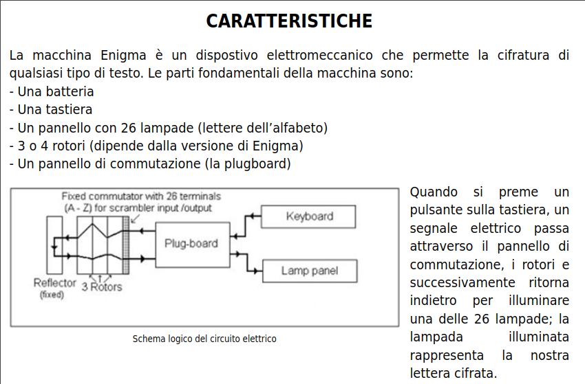
What's cool about the Enigma machine is that it is an electro-mechanical device that implements an extremely complex substitution cipher. That is, it works by using electricity, but it also has parts that move mechanically. This machine was used by the forces of the Axis during the Second World War in order to protect their communications. Since the machine works with the english alphabet, from now on anytime I mention alpabet, think of the following symbols
\[\texttt{ABCDEFGHIJKLMNOPQRSTUVWXYZ}\]
The machine looks as follows
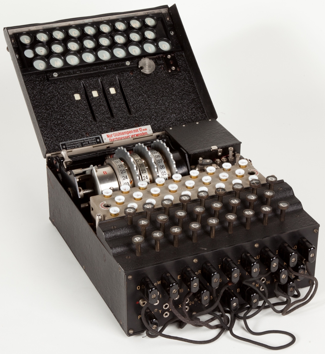
From the photo we can quickly see all of its main components:
-
We have a keyboard made up of the \(26\) letters of the alhpabet
-
We have a lamp panel, made up of \(26\) different lightbulbs, each of which also represent a letter of the alphabet.
-
We have a plugboard in the front, made up of \(10\) cables each of which is used to link together a pair of holes, each of which represents a letter of the alphabet.
-
We have three different rotors, those metallic gears with numbers from \(\texttt{01}\) to \(\texttt{26}\).
-
We have a reflector, with the red label
Bwritten over it.
All the components of the machine are linked together with an electrical circuit, which is showcased in the following image
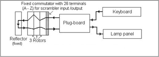
The key idea of enigma is that anytime you press a key, the mechanical part of the machine activates, its rotors move, then the electrical circuit closes, and from the key pressed a specific lightbulb lights up. That lightbulb represent the encrypted letter. For example, if we press \(\texttt{A}\) and the letter \(\texttt{D}\) lights up, then the machine told us to encrypt \(\texttt{A}\) with \(\texttt{D}\), that is, we have the following mapping
\[\texttt{A} \longrightarrow \texttt{D}\]
That is how the mechanical and electrical part of Enigma come together: at anytime the electrical defines a specific substitution cipher that maps each plaintext letter to its corresponding ciphertext pair. When the machines moves mechanically, a different circuit is created, and therefore the cipher changes. This essentially mean that Enigma is a machine made up of an extremely large amount of substitution ciphers which are changed anytime we encrypt a letter. This is also why if you press the same latter, say \(\texttt{A}\), you keep getting different results.
NOTE: Due to the reflector construction, the machine does not allow a letter to be encrypted as itself. This means that if we press \(\texttt{A}\) we will never get \(\texttt{A}\) back as the encrypted letter. While this might not seem such a big deal, it actually was, because it allowed the Allies to quickly understand invalid machine settings and this set up the groundwork for actually breaking the settings and reading the nazis encrypted messages.
To finish off this overview of Enigma, in order to implement the
machine we need to understand in detail the three main components
of the machine, which are plugboard, reflector and rotor. We are
not interested in their mechnical and electrical construction, even
though it was an honorable engineering effort that deserves its own
space. Our objective is to build a full emulator of the Enigma
machine, and thus we will focus in understanding the logical
functioning of each component.
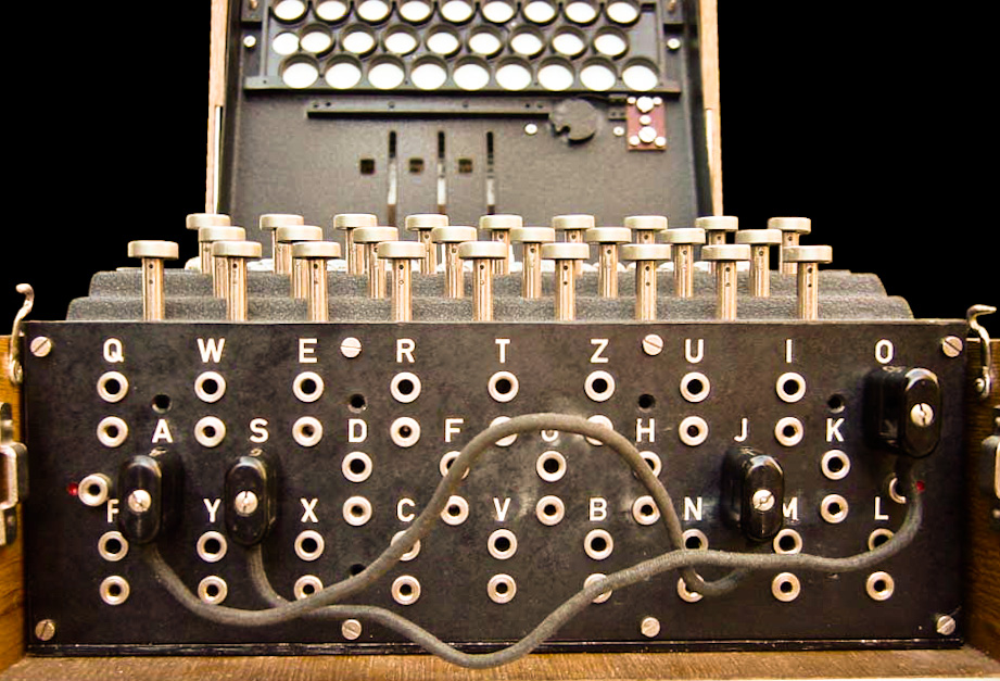
#The Plugboard
The plugboard is used to swap letters. We can use up to \(10\) cables, each of which is used to swap a pair of letter. For example, with no plugboard, if I press \(\texttt{A}\) then the first rotor will receive \(\texttt{A}\) as input. However, if \(\texttt{A}\) is mapped to \(\texttt{F}\) within the plugboard, then the rotor will receive \(\texttt{F}\) as input. This swapping happens in two different places of the encryption process:
-
After the plaintext letter is pressed but before the signal gets to the first rotor.
-
After the last rotor processes the letter but before the lightbulb lights up.
This also means that, assuming the couple \((\texttt{A}, \texttt{F})\) is connected with the plugboard, then if, after enigma has finished to encrypt a letter, the signal that exists from the last rotor is of the letter \(\texttt{F}\), then the lightbulb that lights up is actually \(\texttt{A}\) because the signal has been swapped within the plugboard.
Logically, the plugboard is pretty easy to model. It is just a list of couples, who's length varies from \(0\) to \(10\), and where each letter in the alphabet can appear one time in only one couple. We can describe a plugboard setting as follows
\[(\texttt{A}, \texttt{F}) \;\;,\;\; (\texttt{D}, \texttt{P}) \;\;,\;\; (\texttt{Z}, \texttt{Y})\]
NOTE: The usage of the plugboard drastically increases the number of possible configuration of the enigma machine, and it makes the job of breaking Enigma extremely harder.
#The Reflector
The reflector is used to reflect back the electrical signal. When a letter is pressed, electricity moves from the button pressed to the plugboard, and then to the rotors, starting from the right-most rotor towards the left-most rotor. Then the signal is sent to the reflector, which sends it back to the rotor once again, but this time instead of going from right-to-left, the signal moves in the opposite direction, from left-to-right.
The reflector maps each letter to another letter, acting once as a sort of substitution box. This means that we can model the reflector by specifying how this substitution is performed. To define a reflector we need to specify exactly how each letter of the alphabet is mapped to another letter of the alphabet, with a key characteristics being that no letter can be mapped to itself.
Now, there are various resourcesthat document valuable historical information such as the specific circuits used within the various components of Enigma. During my implementation I used the following
https://www.cryptomuseum.com/crypto/enigma/wiring.htm
For example, in the Enigma M3 model, one of the ones used by the
German Navy, there were two possible reflectors, called
respectively UKW-B and UKW-C, where UWK stands for Umkehrwalze. The
UKW-B defines the following mapping
\[\begin{split} &\texttt{ABCDEFGHIJKLMNOPQRSTUVWXYZ} \\ &\qquad \qquad \qquad \downarrow \\ &\texttt{YRUHQSLDPXNGOKMIEBFZCWVJAT} \\ \end{split}\]
For for example, when using UKW-B, the letter \(\texttt{A}\) will be
mapped to \(\texttt{Y}\), while \(\texttt{W}\) will be mapped to
\(\texttt{V}\) and so on for the other letters.
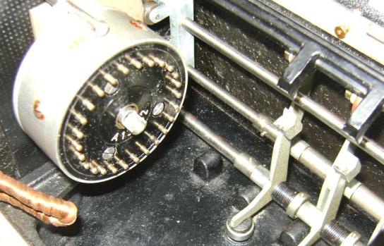
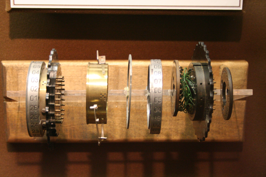
#The Rotor
Finally, we arrive at the rotor, probably the most important element of the Enigma machine.
There are two different aspects of the rotors that must be taken into account:
- Their internal structure
- Their movements
With respect to their internal structure, each rotor acts once again as a substitution box, mapping \(26\) pins from its right to another set of \(26\) pins to its left. Each pin represent a specific letter of the alphabet. So, once again, the key idea here to understand is that of substitution. When a letter goes into a given rotor on its right, it will come out as a different letter on its left.
Remember that also the reflector acts as a substitution box. There are a couple of differences between a rotor and a reflector. These are listed below:
-
While the reflector is used only in a single direction, the rotor can be used in two different directions: from right to left, and from left to right. Depending on the direction, the mapping will be different.
-
The rotor can move, and each time it moves the internal wirings change, which means that a different substitution will take place.
-
The rotor has a special place called the notch, which is used to drive the movements of the rotors that sits on its left.
-
Finally, the rotor internal wiring can receive an initial offset with respect to its external pins by changing the so-called ring-setting (originally called
Ringstellung)
So for example, consider the V rotor used by Enigma M3. Its wiring
is defined by the following substitution
\[\begin{split} &\texttt{ABCDEFGHIJKLMNOPQRSTUVWXYZ} \\ &\qquad \qquad \qquad \downarrow \\ &\texttt{VZBRGITYUPSDNHLXAWMJQOFECK} \\ \end{split}\]
It means that initially, at rest, if on the right-pin the letter \(\texttt{A}\) activates, then on its left-pin the letter \(\texttt{V}\) activates. If however the letter \(\texttt{A}\) actiates on the left-pin, then on the right-pin the letter \(\texttt{Q}\) will activate.
As it was clear from the initial picture of Enigma, most Enigma machines do not have a single rotor, but rather three rotors in a row. This means that the pins of one rotors are connected to the pins of the next rotor in the row. All the rotors work the same, but just remember, there are three in a row, and each one can be used in two different directions.
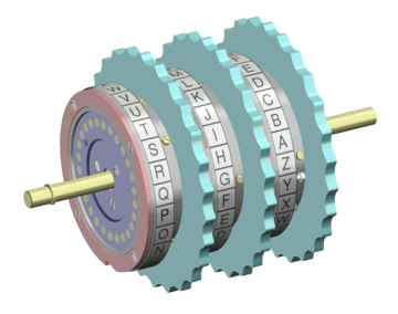
This is why during the war various Rotors were manufactured. Before using Enigma the soldiers had to choose in which order to place the three different rotors, something that increased by a factor of \(60\) the number of different configurations.
The last we need to discuss when it comes to rotor is the way the rotors move. This is because everytime we press a letter, before the circuit is closed, a mechanical movement is performed by the right-most rotor, and then, sometimes, also the middle rotor and the left-most rotor move. It is only after the movement has finished that the electrical circuit closes and you get one of the lightbulb to light up.
The movement is performed as follows.
-
The right rotor moves at each letter pressed.
-
The middle rotor moves only when the right rotor has reached a particular position, called the notch. Typically there is only a single notch per rotor, which means that the middle rotor moves one step forward every \(26\) steps of the right rotor.
-
The same idea also applies for the left rotor. It only moves when the notch of the middle is exposed. However, there is a special thing that happens here, which is called the double-step mechanism, and is a crucial little detail to capture in order to have a proper emulator. The idea is that when the middle rotor exposes its notch, then in the next round the left will move. However, if the middle rotor does not move also, it will keep exposing its notch, which means that the left rotor will keep moving again. To avoid this undesired behavior, in the round after the middle rotor exposes its notch, both the left and middle rotor moves, so that the notch of the middle rotor is once again hidden.
The double-step mechanism is showcased in the following video
https://www.youtube.com/watch?v=hcVhQeZ5gI4
#The Code
We can now start describing the code we will implement. In this section I will also let the code talk, and I will explain only the assumption that I've made that are not explicitly shown in the code. If at anytime you feel lost, you can checkout the final code within my github repository, linked here.
https://github.com/LeonardoE95/enigma-machine
#Header-only library
The idea is to implement a header-only library. This means that
all the code will fit inside a enigma.h file. Within that file we
will have two different sections:
- The header portion
- The implementation portion
The skeleton will be as follows
#ifndef ENIGMA_H_
#define ENIGMA_H_

// header portion

#endif // ENIGMA_H_

#ifdef ENIGMA_IMPLEMENTATION

// implementation  portion

#endif // ENIGMA_IMPLEMENTATION
When someone wants to use the library, they can just import the
enigma.h while having defined the pre-processor symbol
ENIGMA_IMPLEMENTATION, which will include also the implementation
#define ENIGMA_IMPLEMENTATION
#include "../enigma.h"
#Typedefs and libraries
In terms of libraries, the ones we need are shown below
#include <assert.h>
#include <stdint.h>
#include <string.h>
#include <stdint.h>
#include <stdlib.h>
We then have the following initial typedefs, which will make the code cleaner to read
typedef uint8_t u8
typedef size_t usize
#Public API
The idea is to offer the following public API.
void enigma_encrypt(Enigma* e,
		    const char* plaintext,
		    usize plaintext_len,
		    char* ciphertext);

void enigma_decrypt(Enigma* e,
		    const char* ciphertext,
		    usize ciphertext_len,
		    char* plaintext);

Enigma *init_enigma(const char *rotor_names[ROTORS_N],
		    const u8 rotor_positions[ROTORS_N],
		    const u8 rotor_ring_settings[ROTORS_N],
                    const char *reflector_name,
		    u8 (*plugboard)[2],
                    usize plugboard_size);

void destroy_enigma(Enigma *e);
Here the user is supposed to handle the memory needed to deal with
both the plaintext and the ciphertext, and the library has to
simply fill in the ciphertext array, which is assumed to be of
length equal to the plaintext.
An example usage of our library is shown below.
-
Initialize the machine
Enigma *e = init_enigma ( // rotor models (const char *[]){"M3-II", "M3-I", "M3-III"}, // rotor positions (const u8 [ROTORS_N]) {0, 0, 0}, // rotor ring settings (const u8 [ROTORS_N]) {0, 0, 0}, // reflector model "M3-B", // plugboard switches (u8 [][2]){ {'A', 'M'}, {'F', 'I'}, {'N', 'V'}, {'P', 'S'}, {'T', 'U'}, {'W', 'Z'}, }, // plugboard size 6 ); -
Prepare string buffers
char *str = "HELLO"; usize length = strlen(str); char *plaintext = malloc(length * sizeof(char)); char *ciphertext = malloc(length * sizeof(char)); strncpy(plaintext, str, length); strncpy(ciphertext, plaintext, length); -
Perform encryption
enigma_encrypt(e, plaintext, length, ciphertext);
#Data Structures
In terms of data structures, we start by defining some macros
#define ALPHABET_SIZE 26
#define PLUGBOARD_SIZE 10
#define ROTORS_N 3
#define LABEL_LENGTH 42
A key concept we need to capture is the idea of substitution, which
we will now call a wiring. For us a Wiring is an array of
ALPHABET_SIZE of u8
typedef u8 Wiring[ALPHABET_SIZE];
We only care about u8 because we're only interested in
numerical values. We can abstract away the letters and just work
with numbers from \(0\) to \(25\). For example, suppose we want to
represent the following wiring
\[\begin{split} &\texttt{ABCDEFGHIJKLMNOPQRSTUVWXYZ} \\ &\qquad \qquad \qquad \downarrow \\ &\texttt{VZBRGITYUPSDNHLXAWMJQOFECK} \\ \end{split}\]
We can represent that wiring with the following array made up of twenty six numbers, each of which is between \(0\) and \(25\).
{
   21, 25, 1, 17, 6, 8, 19, 24, 20, 15,
   18, 3, 13, 7, 11, 23, 0, 22, 12, 9,
   16, 14, 5, 4, 2, 10
}
For example, the fact that the element at index \(0\) is \(21\) represent that \(\texttt{A}\) goes to \(\texttt{V}\), or the fact that the element at index \(16\), which is \(0\) represents the fact that \(\texttt{Q}\) goes to \(\texttt{A}\).
To implement this we use the following two macros which allow us to
move between char and code. For us the char will be the typical
ASCII letter, such as \(\texttt{A}, \texttt{B}\) and so on, while
code are numbers from \(0\) to \(25\).
#define CHAR2CODE(ch) ((u8) ((ch) - 'A'))
#define CODE2CHAR(code) ((char) ('A' + (code)))
NOTE: In the way this is currently implemented, this means that our implementation only supports capital letters. By changing this you can also extend it to represent a more complex charset.
Continuing, the core structure we will work with, the Enigma structure, is defined as follows
typedef struct {
  Plugboard plugboard;
  Rotor rotors[ROTORS_N];
  Reflector reflector;
} Enigma;
where here we have the three main components of Enigma
-
Plugboard
typedef struct { u8 board[PLUGBOARD_SIZE][2]; usize board_size; } Plugboard; -
Reflector
typedef struct { Wiring wiring; char name[LABEL_LENGTH]; } Reflector; -
Rotor
Notice that for the rotor we need two wirings, one for the forward direction and one for the backward direction.
  typedef struct {
    Wiring forward_wiring;
    Wiring backward_wiring;
    u8 position;
    u8 notch;
    u8 ring;
    char name[LABEL_LENGTH];
  } Rotor;
To represent the two different directions we can use an enum
  typedef enum {
    RO_FORWARD,
    RO_BACKWARD,
  } RotorOrder;
#Historical Models
In order to have a quick way to remember the historical Enigma
models, we can define two data structures, namely RotorModel and
ReflectorModel
typedef struct {
  char name[LABEL_LENGTH];
  char wiring[ALPHABET_SIZE];
  u8 notch;
} RotorModel;
typedef struct {
  char name[LABEL_LENGTH];
  char wiring[ALPHABET_SIZE];
} ReflectorModel;
and we can fill two arrays defined as global variables
RotorModel KNOWN_ROTORS[] = {
  {"M3-I", "EKMFLGDQVZNTOWYHXUSPAIBRCJ", CHAR2CODE('Q')},
  {"M3-II", "AJDKSIRUXBLHWTMCQGZNPYFVOE", CHAR2CODE('E')},
  {"M3-III", "BDFHJLCPRTXVZNYEIWGAKMUSQO", CHAR2CODE('V')},
  {"M3-IV", "ESOVPZJAYQUIRHXLNFTGKDCMWB", CHAR2CODE('J')},
  {"M3-V", "VZBRGITYUPSDNHLXAWMJQOFECK", CHAR2CODE('Z')},
};

usize KNOWN_ROTORS_LENGTH = (sizeof(KNOWN_ROTORS)/sizeof(RotorModel));
ReflectorModel KNOWN_REFLECTORS[] = {
  {"M3-A", "EJMZALYXVBWFCRQUONTSPIKHGD"},
  {"M3-B", "YRUHQSLDPXNGOKMIEBFZCWVJAT"},
  {"M3-C", "FVPJIAOYEDRZXWGCTKUQSBNMHL"},
};

usize KNOWN_REFLECTORS_LENGTH = (sizeof(KNOWN_REFLECTORS)/sizeof(ReflectorModel));
#Core Functions
With respect to the core functions we will first see how to implement the public API. Both of these functions will call an internal function called apply_enigma.
void enigma_encrypt(Enigma* e, const char* plaintext, usize plaintext_len, char* ciphertext) {
  assert(plaintext_len == strlen(ciphertext) && "enigma_encrypt(): strlen(ciphertext) != plaintext_len");
  apply_enigma(e, (const u8*)plaintext, plaintext_len, (u8*) ciphertext);
#ifdef ENIGMA_DEBUG
  printf("[INFO] enigma_encrypt(): '%s' -> '%s'\n", plaintext, ciphertext);
#endif
}
void enigma_decrypt(Enigma *e, const char *ciphertext, usize ciphertext_len, char *plaintext) {
  assert(ciphertext_len == strlen(plaintext) && "enigma_encrypt(): strlen(ciphertext) != plaintext_len");
  apply_enigma(e, (const u8*)ciphertext, ciphertext_len, (u8*)plaintext);
#ifdef ENIGMA_DEBUG
  printf("[INFO] enigma_decrypt(): '%s' -> '%s'\n", ciphertext, plaintext);
#endif
}
The core logic of the enigma encryption algorithm is implemented within the apply_enigma function. Notice how the movement is executed before the encryption of each letter.
void apply_enigma(Enigma *e, const u8 *input, usize input_len, u8 *output) {
  // Assumes output has been already allocated
  //
  // string and that len(output) == input_len
  //
  for (usize i = 0; i < input_len; i++) {
    u8 input_char = input[i];

    // Transform character into char_code
    u8 char_code = CHAR2CODE(input_char);

    // Movement is executed before encryption
    move_rotors(e);

    // FORWARD PASS
    char_code = apply_plugboard(e, char_code);
    char_code = apply_rotors(e, char_code, RO_FORWARD);

    // REFLECTOR
    char_code = apply_reflector(e, char_code);

    // BACKWARD PASS
    char_code = apply_rotors(e, char_code, RO_BACKWARD);
    char_code = apply_plugboard(e, char_code);

    // Transform char_code into character
    u8 output_char = CODE2CHAR(char_code);

    output[i] = output_char;
  }
}
Notice how this function internally calls other functions. The signatures of these functions are shown below
void move_rotors(Enigma *e);

u8 apply_rotor(Rotor *r, const u8 plaintext_code, RotorOrder order);
u8 apply_rotors(Enigma *e, const u8 plaintext_code, RotorOrder order);
u8 apply_plugboard(Enigma *e, const u8 plaintext_code);
u8 apply_reflector(Enigma *e, const u8 plaintext_code);
First we deal with the movement of the rotors. This function uses
the notch configuration of the various rotors with respect to the
rotor position.
void move_rotors(Enigma *e) {
  // https://en.wikipedia.org/wiki/Enigma_machine
  // https://www.youtube.com/watch?v=ds8HoowfewA
  //
  // Double stepping caused by the claw mechanism used for rotating
  // the rotors makes the second rotor move twice in a row, if the
  // first movement brings it in the turnover position during the
  // first rotation.
  //
  //  https://www.youtube.com/watch?v=5StZlF-clPc
  //  https://www.youtube.com/watch?v=hcVhQeZ5gI4
  //
  if (e->rotors[1].position == e->rotors[1].notch) {
    e->rotors[2].position = (e->rotors[2].position + 1) % ALPHABET_SIZE;
    e->rotors[1].position = (e->rotors[1].position + 1) % ALPHABET_SIZE;
  } else if (e->rotors[0].position == e->rotors[0].notch) {
    e->rotors[1].position = (e->rotors[1].position + 1) % ALPHABET_SIZE;
  }
  e->rotors[0].position = (e->rotors[0].position + 1) % ALPHABET_SIZE;
}
Then we apply the single rotor with a given order. This function
internally uses the ring and position in order to change how the
internal wiring is being used depending on the current rotor
configuration.
u8 apply_rotor(Rotor *r, u8 char_code, RotorOrder order) {
  char_code = (char_code - r->ring + r->position + ALPHABET_SIZE;) % ALPHABET_SIZE;
  if (order == RO_FORWARD)  {
    char_code = r->forward_wiring[char_code];
  } else if (order == RO_BACKWARD) {
    char_code = r->backward_wiring[char_code];
  } else {
    assert(0 && "Unreachable");
  }
  char_code = (char_code + r->ring - r->position + ALPHABET_SIZE;) % ALPHABET_SIZE;

  return char_code;
}
u8 apply_rotors(Enigma *e, u8 char_code, RotorOrder order) {
  switch(order) {

  case RO_FORWARD: {
    char_code = apply_rotor(&e->rotors[0], char_code, RO_FORWARD);
    char_code = apply_rotor(&e->rotors[1], char_code, RO_FORWARD);
    char_code = apply_rotor(&e->rotors[2], char_code, RO_FORWARD);
  } break;

  case RO_BACKWARD: {
    char_code = apply_rotor(&e->rotors[2], char_code, RO_BACKWARD);
    char_code = apply_rotor(&e->rotors[1], char_code, RO_BACKWARD);
    char_code = apply_rotor(&e->rotors[0], char_code, RO_BACKWARD);
  } break;

  default: assert(0 && "apply_rotors(): Unreachable");
  }

  return char_code;
}
In a similar but much simpler way we also apply the reflector
u8 apply_reflector(Enigma *e, const u8 plaintext_code) {
  return e->reflector.wiring[plaintext_code];
}
Finally, we can apply the plugboard.
u8 apply_plugboard(Enigma *e, const u8 plaintext_code) {
  for (usize i = 0; i < e->plugboard.board_size; i++) {
    if (plaintext_code == e->plugboard.board[i][0]) {
      return e->plugboard.board[i][1];
    } else if (plaintext_code == e->plugboard.board[i][1]) {
      return e->plugboard.board[i][0];
    }
  }
  return plaintext_code;
}
#Initialization
To finish the description of the code, we can deal with the initialization functions, who's role is to initialize the data structure and the memory needed to perform the encryption and decryption operation.
We start with init_enigma, the main initialization function which
is used to create an enigma machine. This function also forms part
of the public API
Enigma *init_enigma(const char *rotor_names[ROTORS_N],
		    const u8 rotor_positions[ROTORS_N],
		    const u8 rotor_ring_settings[ROTORS_N],
                    const char *reflector_name,
		    u8 (*plugboard)[2],
                    usize plugboard_size) {

  if (plugboard_size > PLUGBOARD_SIZE) {
    printf("[ERROR]: init_enigma() - supplied plugboard size (%ld) greater than maxium (%d)\n", plugboard_size, PLUGBOARD_SIZE);
    exit(0);
  }

  Enigma *e = calloc(1, sizeof(Enigma));

  init_rotors(e, rotor_names, rotor_positions, rotor_ring_settings);
  init_reflector(e, reflector_name);
  init_plugboard(e, plugboard, plugboard_size);

  return e;
}
We then have the functions which initialize the various components.
We start by initializing the rotors with the init_rotors
// We specify rotors in the init array from left to right. Given
// however that the most frequent rotor is the right-most rotor, we
// save that on index-0.
void init_rotors(Enigma *e,
		 const char *rotor_names[ROTORS_N],
		 const u8 rotor_positions[ROTORS_N],
		 const u8 rotor_ring_settings[ROTORS_N]) {

  for (usize i = 0; i < ROTORS_N; i++) {
    init_rotor(&e->rotors[i],
	       rotor_names[ROTORS_N - 1 - i],
	       rotor_positions[ROTORS_N - 1 - i],
	       rotor_ring_settings[ROTORS_N - 1 - i]);
  }

}
The single rotor is then initialized within init_rotor. Here we
used the rotor_name and we iterate over all historically used
rotors to check if we have a match. When we find a match we use
the functions init_wiring and reverse_wiring to initialize the
wiring.
void init_rotor(Rotor *r, const char *rotor_name, const u8 position, const u8 ring) {
  u8 found = 0;

  // Here we assume that
  for(usize i = 0; i < KNOWN_ROTORS_LENGTH; i++) {
    if (strcmp(KNOWN_ROTORS[i].name, rotor_name) == 0) {
      found = 1;

      char *known_name    = KNOWN_ROTORS[i].name;
      char *known_wiring  = KNOWN_ROTORS[i].wiring;
      u8    known_notch   = KNOWN_ROTORS[i].notch;

      init_wiring(r->forward_wiring, known_wiring, ALPHABET_SIZE);
      reverse_wiring(r->backward_wiring, r->forward_wiring, ALPHABET_SIZE);

      r->notch = known_notch;
      r->position = position;
      r->ring = ring;

      // copy also NULL-terminating byte
      memcpy(r->name, known_name, strlen(known_name) + 1);

      break;
    }
  }

  if (!found) {
    assert(0 && "init_rotor(): unsupported rotor\n");
  }
}
The init_wiring and reverse_wiring are implemented as follows
void init_wiring(Wiring wiring, const char *alphabet, usize alphabet_len) {
  for (usize i = 0; i < alphabet_len; i++) {
    wiring[i] = CHAR2CODE(alphabet[i]);
  }
}
// Used to change the direction of old_wiring into new_wiring.
//
// old_wiring[X] = Y if and only if old_wiring[Y] = X
//
void reverse_wiring(Wiring new_wiring, Wiring old_wiring, usize wiring_len) {
  for(usize i = 0; i < wiring_len; i++) {
    new_wiring[old_wiring[i]] = (u8)i;
  }
}
Continuing, we initialize the reflector
void init_reflector(Enigma *e, const char *reflector_name) {
  u8 found = 0;

  for (usize i = 0; i < KNOWN_REFLECTORS_LENGTH; i++) {
    if (strcmp(KNOWN_REFLECTORS[i].name, reflector_name) == 0) {
      found = 1;

      char *known_name   = KNOWN_REFLECTORS[i].name;
      char *known_wiring = KNOWN_REFLECTORS[i].wiring;

      init_wiring(e->reflector.wiring, known_wiring, ALPHABET_SIZE);

      // copy also NULL-terminating byte
      memcpy(e->reflector.name, known_name, strlen(known_name) + 1);
    }
  }

  if (!found) {
    assert(0 && "init_reflector(): unsupported reflector\n");
  }

}
And finally, we initialize the plugboard
void init_plugboard(Enigma *e, u8(*board)[2], usize plugboard_size) {
  e->plugboard.board_size = plugboard_size;
  for(usize i = 0; i < plugboard_size; i++) {
    e->plugboard.board[i][0] = CHAR2CODE(board[i][0]);
    e->plugboard.board[i][1] = CHAR2CODE(board[i][1]);
  }
}
#Destruction
The last thing we need to implement is the function needed to clean up the memory allocated during the initialization of the enigma machine.
void destroy_enigma(Enigma *e) {
  if (e) {
    free(e);
  }
}
#Enigma CLI
In order to use efficiently the machine, I have also developed a small shell that allows us to configure and use the enigma machine. To compile it, clone the github repo and execute the following
git clone https://github.com/LeonardoE95/enigma-machine
cd enigma-machine
make examples
./examples/cli
We can then use the following commands
Enigma> help
Enigma> List of commands...

        quit – exit from enigma cli
        help – list available commands
        info – print enigma configuration
        set <rotors> | set <reflector> | set <plugboard> – change enigma configuration
        encrypt <plaintext> – encrypt plaintext
        decrypt <ciphertext> – decrypt ciphertext
For example, this is the initial configuration
Enigma> info
Enigma> Current configuration...
        Rotors (from left to right): M3-II, M3-I, M3-III
               Position: 0, 0, 0
                   Ring: 0, 0, 0
        Reflector: M3-B
        Plugboard: 6 plugs
                   (A, M)
                   (F, I)
                   (N, V)
                   (P, S)
                   (T, U)
                   (W, Z)
to encrypt a string such as HELLO
Enigma> encrypt HELLO
MIJEN
to instead set a custom configuration you can use the set command
Enigma> set reflector M3-B
Enigma> set rotor left M3-I 1 2
Enigma> set rotor middle M3-II 3 4
Enigma> set rotor right M3-III 5 6
Enigma> set plugboard B-Q C-R
Enigma> info
Enigma> Current configuration...
        Rotors (from left to right): M3-I, M3-II, M3-III
               Position: 1, 3, 5
                   Ring: 2, 4, 6
        Reflector: M3-B
        Plugboard: 2 plugs
                   (B, Q)
                   (C, R)
Enigma> encrypt DSFSDFSDF
SCLMEEYMV
And that's it. In the future, if I find the time, I would really like to understand how enigma was broken and maybe implement the some of the ideas in code. If I managed to do that I will try to write about it as well. For now, if you have any feedback on my implementation please let me know, and I wish you a good programming time!